


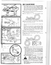
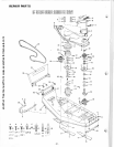

RETAINER
cf
IDLER
SPRING
...._.,
SHAFT
ASSEMBLY
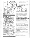
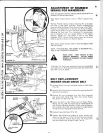
FIGURE 18
ELT
GUIDE
UPPER
~~~~~
CENTER
MANDREL:
SHEAVE
BELT
GUIDE
N
UT
S
FIGURE 19
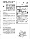
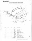
E
NG
INE
-----
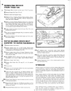
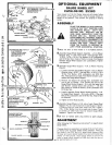
PULLEY
ADJUSTMENT
OF
SNUBBER
[BRAKE FOR MANDRELS)
After
belt
has been
properly
adjusted, adjust
Adjusting
Pin
on
Snubber
Pu
ll
Rod
as
stated below:
Place
Mower
Clu
tch
Control
Le
ve
r
in
"OUT"
po
si
t
io
n (Fig.
7A
).
Remove Retainer
Sp
ring
ho
lding
Adjusting
Pi
n
on
Snubber
Pull Rod in Idler Sh
aft
Assembly. Remove
Adjusting
Pin
fro
m
ho
le. With the Mo
wer
C
lut
ch
Contro
l Lever
in
the
"OUT"
Posit
io
n.
tu
rn
Adjusting
Pin on
Sn
ubber Pull Rod
un
til
Adjust
-
ing Pin
will
fit
freely in ho
le
of
Id
le
r S
haft
Assembly. Remove
Adjust
ing Pin
from
hole.
Turn
Adjusti
ng Pin
counterclock
-
wise 6 complete
turns
and rep
lace
Washer
on
Pin
against
shoulder. Reinsert
Pin
with
Washe
r in hole
of
Idler
Shaft
Assem
bly.
NOTE
: Mower
Clutch
Cont
rol Lever can
be
pulled
ahead
to
assemble. Secure
with
Retainer Spring.
When
Mower
Clutch Control Lever
is
fully
di
sengag
ed
, blades
will
stop
quick
l
y.
NOTE:
TRACTOR
WILL
NOT
START
IF SNUBBER
PULL
ROD IS N
OT
PROPER
LY
ADJUSTED.
MAKE
SURE
THAT
BRAKE
IS NOT
AGAINST
MANDREL
PULLEY
WHEN
MOWER
IS
ENGAGED (LEVER PUSHED
FORWARD).
If
Snubber Pull Rod
is
ever removed,
be
sure
it
is
reassembled
with
slight bend in Rod
downward
and under
the
mower
drive
'&
belt. Refer
to
Fig. 9,
page
4.
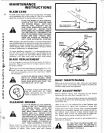
BELT
REPLACEMENT
MOWER
MAIN DRIVE
BELT
1.
Unhook
Spring
from
rear
be
lt
guide bracket
of
Be
lt Guide
(Fig.
19).
2. Remove Belt Guide
at
center mandrel
by
removing three (3)
Nuts and Lockwashers.
3. Remove Nut and Lockwasher
fr
om
Idler Shaft Assembly
and remove Belt Guide (Fig.
19A)
. Al
so
remo
ve
Engine
Belt
Guard and
Be
lt
(Fig.
18).
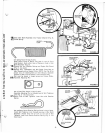
4. Install new Belt
on
Idl
er
Sheaves
and
on
Engine Pulley.
-8-
NOTE:
See
Fig.
19A
for
proper
way
of
installing Belts
on
Idler
Sheaves
. Backside (outside)
of
Belt
must
be
placed in
flat
(outside) Idler. Belt
must
be
placed in largest groove
of
Engine Pulley. Replace
Belt
Guide secure
ly.
5. Replace Engine
Bel
t Guard (Fig.
18).
6. Replace
Belt
Guide and snubber
at
center mandrel and
adjust
so
that there
is
1/16
to
1/8
inch clearance between
it
and the
Sheave
. Replace Spring (Fig. 19).
Adjust
drive
ti..,
belt
and snubber refer
to
page
4,
steps 1
thr
u 8.
another free manual from www.searstractormanuals.com