


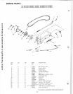

-.g:;-.,.....,,£:~-:Jb:,....CARRIAGE
BOLTS
5/16
x
3/4
FIGURE
1
FLAT
WASHERS
11/32
x
11/16
x
16
GA.
LOCKWASHERS
5/16
HEX
NUTS
5/16
IAICARRIAGE
BOLT
5/16
x 1
FLAT
WASHER
11/32
X
11/16
X
16
GA.
LOCKWASHER
5/16
HEX
NUT5/16
--~
GAUGE
WHEEL
SUPPORT • R.H.
THICKER
PORTION
OF
HUB
TOWARD
GAUGE
WHEEL SUPPORT
(C)
CARRIAGE
BOLT
5/16
x 1
LOCKWASHER
5/16
HEX
NUT
5/16
RUNNER · R.H.
EX
NUT
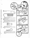
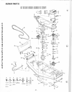
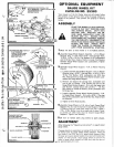
OPTIONAL EQUIPMENT
GAUGE WHEEL
KIT
CATALOG
NO.
25383
Your
mower
is
of
the
full
floater
type
and
will closely
follow
the
contours
of
the
ground
when
using
the
gauge wheels
for
height
of
cut
position.
They
prevent
soil gouging
on
sloping
terrain.
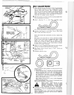
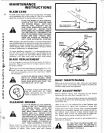
ASSEMBLY
PLACE
THE
MOWER CLUTCH
CONTROL
LEVER IN
THE
"OUT"
POSITION, LOCK
THE
PARKING
BRAKE,
SHIFT
INTO
NEUTRAL
AND
SHUT-OFF
THE
EN-
GINE.
MAKE ABSOLUTELY
SURE
THE
BLADES
AND
ALL
MOVING
PARTS
HAVE COMPLETELY
STOPPED.
REMOVE
THE IGNITION
KEY,
DISCONNECT
THE
SPARK PLUG WIRE(S)
FROM
THE
SPARK
PLUG(S)
AND
KEEP WIRE(S) AWAY
FROM
THE
PLUG(S)
TO
PREVENT
IN·
JURY
FROM
ACCIDENTAL
STARTING.
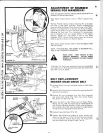
1.Move
lift lever
so
that
mower
is
in its highest position.
2.Assemble
Gauge Wheel
Support
Assembly - L.H.
to
Mower
Housing (Fig.
1)
with
three
5/16
x
3/4
Carriage Bolts,
11/32 x 11/16 x
16
Ga.
Flat
Washers,
5/16
Lockwashers
and
5/16
Hex Nuts. Heads
of
Bolts
to
inside;
Flat
Washers
between
Gauge Wheel
Support
and
Lockwashers. Tighten
nuts
securely.
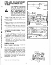
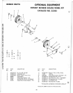
3.Assemble
Gauge Wheel
Support
· R.H.
to
Mower Housing
(Fig.
2).
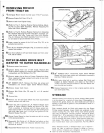
a. Loosely assemble Gauge Wheel
Support·
R.H.
to
Mower
Housing using a
5/16
x 1 Carriage Bolt,
11
/32
x 11/16 x
16 Ga.
Flat
Washer,
5/16
Lockwasher
and
5/16
Hex
Nut.
Head
of
bolt
to
inside; Flat Washer
between
Lock·
washer
and
Gauge Wheel
Support.
b. Remove
and
discard
the
carriage
bolt,
lockwasher
and
nut
at
rear
of
Runner
- R.H. Position
the
end
of
the
Gauge Wheel Bracket
Support·
R.H.
with
the
larger
hole
over
Runner.
Loosely secure
with
a
5/16
x 1 · 1/4 Hex
Bolt
(head
to
outside
as
shown),
5/16
Lockwasher
and
5/16
Hex
Nut.
c. Loosely assemble Gauge Wheel Bracket
Support
· R.H.
to
Gauge Wheel
Support
- R.H.
with
a
5/16
x 1 Carriage
Bolt,
5/16
Lockwasher
and
5/16
Hex
Nut.
Head
of
bolt
to
underside.
d.
Tighten all
three
Nuts securely.
4.Assemble
Gauge Wheels
to
R.H. side
of
each
Gauge Wheel
Support
(Fig. 3). Use t
he
top
hole
in
each
Support.
NOTE:
A Bushing
must
be inside
each
wheel
hub
and
a 13/32 x
7/8
x 14 Ga. Washer
must
be
on
each
side
of
wheel.
Thick·
er
portion
of
wheel
hubs
must
be
toward
Gauge Wheel
Supports
. Tighten nuts securely.
5.Be
sure
to
replace
spark
plug wire(s)
to
spark
plug(s).
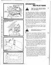
ADJUSTMENT
After
following
the
"Operating
Instructions"
on
page 6
adjust
gauge wheels.
If gauge wheels are
suspended,
no
tearing
of
the
turf
will
occur
on
sharp
turns
by gauge wheels sliding sideways.
There
are
four
holes
in
the
R.H. and L.H. gauge wh
ee
l s
uppo
rts
. With
lift
lever
set
to
give desired height
of
cut
and
with
tractor
and
mower
on
level
ground,
adjust gauge wheels
to
one
of
the
FIGURE
3
holes
in
gauge wheel
supports
so
tha't
they
clear
the
ground
li.i.liiiiiiliilii.----------------··15
_by
approximately
3/4 inch.
another free manual from www.searstractormanuals.com