7. Install the 3/8" flatwasher and the
3/8" nylon Iocknut loosely on the
eye bolt.
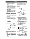
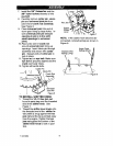
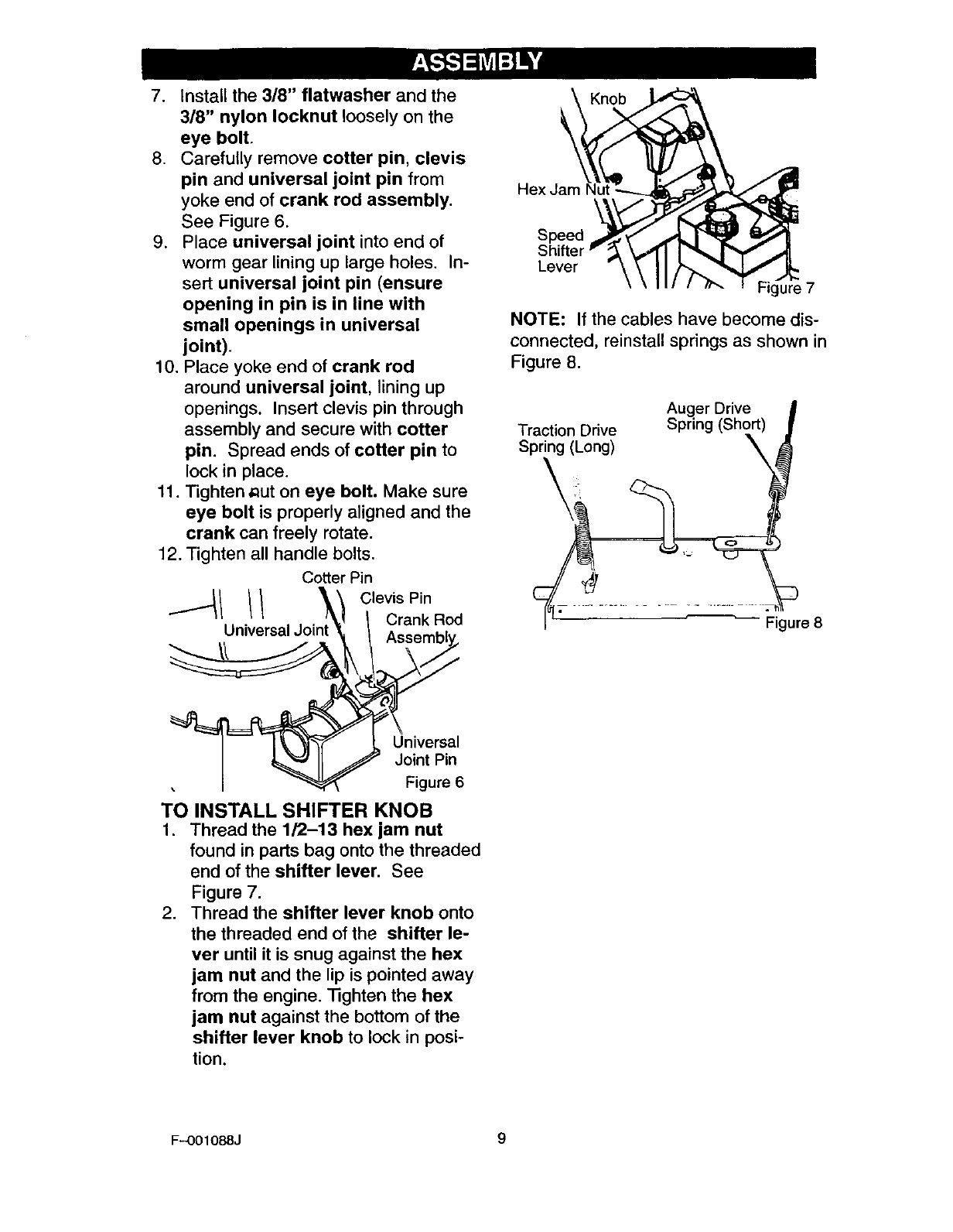
8. Carefully remove cotter pin, clevis
pin and universal joint pin from
yoke end of crank rod assembly.
See Figure 6.
9. Place universal joint into end of
worm gear lining up large holes. In-
sert universal joint pin (ensure
opening in pin is in line with
small openings in universal
joint).
10. Place yoke end of crank rod
around universal joint, lining up
openings. Insert clevis pin through
assembly and secure with cotter
pin. Spread ends of cotter pin to
lock in place.
11. Tighten aut on eye bolt. Make sure
eye bolt is properly aligned and the
crank can freely rotate.
12. Tighten all handle bolts.
Cotter Pin
// o,ev,sPin
Universal Joi Crank Rod
Univer a
Joint Pin
Figure 6
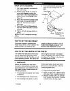
TO INSTALL SHIFTER KNOB
1. Thread the 1/2-13 hex jam nut
found in parts bag onto the threaded
end of the shifter lever. See
Figure 7.
2. Thread the shifter lever knob onto
the threaded end of the shifter le-
ver until it is snug against the hex
jam nut and the lip is pointed away
from the engine. Tighten the hex
jam nut against the bottom of the
shifter lever knob to lock in posi-
tion.
Knob
Hex Jam
Speed
Shifter
Lever
ure 7
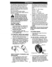
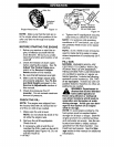
NOTE: If the cables have become dis-
connected, reinstall springs as shown in
Figure 8.
Auger Drive
Traction Drive Spring (Short)
Spring (Long)
igure 8
F-001088J 9


