


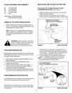
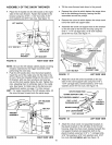
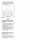

ASSEMBLY OF THE SNOW THROWER • Tilt the snow thrower back down to the ground.
Place the lift handle into the lift bracket on the right
side of the snow thrower. Fasten the handle to the
bracket using two 5/16" x 1-3/4" hex bolts, 5/16"
lock washers and 5/16" hex nuts. See figure 15.
LIFT HANDLE _.
/
5116" LOCK
WASHER
l
5/16" x 1-3/4"
HEX BOLT
LIFT BRACKET
FIGURE 15 RIGHT SIDE VIEW
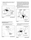
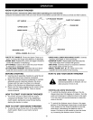
NOTE: Be sure the lift release cable's plastic covering
remains inserted into the trigger assembly while
performing the next step.
• Push the lift handle down into the locked position.
Insert the end of the cable wire into the hole in the
lift rod. Place the threaded fitting into the slot in the
lift bracket, with one hex nut above and one hex
nut and the lock washer below the slot. Tighten the
nuts, adjusting them to eliminate slack in the cable
wire. See figure 16. Refer also to the Service and
Adjustments section on page 17 in this manual.
HINT: For easier assembly of the lift release cable, tilt
the snow thrower forward onto the spiral auger.
LIFT RELEASE
CABLE
TRIGGER
ASSEMBLY
FIGURE 16
HEX NUT
LOCK
WASHER
HEX NUT
;ABLE
WIRE
LIFT
ROD
RIGHT SIDE VIEW
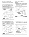
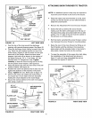
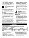
Remove the nylon tie which fastens the auger drive
belt to the discharge housing, leaving the belt
assembled around the pulleys.
Remove the nylon tie which fastens the chute crank
rod to the crank rod support tube.
Assemble the crank rod support tube to the bracket
on the left side of the thrower housing using two
5/16" x 1-1/4" carriage bolts, 5/16" lock washers
and 5/16" hex nuts. See figure 17.
\ \
5/16" HEX NUT
FIGURE 17
CRANK ROD
_UPPORT TUBE
LEFT SIDE VIEW
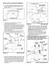
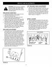
Attach the chute tilt control assembly to the top
side of the crank support tube using two 5/16" x
1-3/4" carriage bolts, bowed washers, 5/16" lock
washers and 5/16" hex nuts. See figure 18.
CHUTE CRANK ROD
CRANK SUPPORT TUBE
TILT CONTROL HANDLE
5/16" x 1-3/4"
CARRIAGE BOLT
BOWED WASHER
5/16" LOCKWASHER
_16"HEX NUT
TILT
CONTROL
ASSEMBLY
FIGURE 18 LEFT SIDE VIEW
lO
Attach the chute crank rod assembly brackets to
the plastic bracket on the left side of the thrower
housing. Align the chute crank bracket beneath the
rod support bracket and assemble both to the
plastic bracket using two 5/16" x 1" carriage bolts,
5/1 6" flat washers, 5/1 6" lock washers and 5/1 6"
hex nuts. Do not tighten yet. See figure 19.