


ASSEMBLY OFTHE SNOWTHROWER
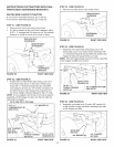
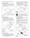
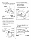
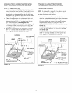
STEP 48: (SEE FIGURE 47)
* Place the lift handle into the lift bracket on the right side
of the snow thrower. Fasten the handle to the bracket
using two 5/16" X 1-3/4" he× bolts (D) and 5/16" Ny[ock
nuts (CO).
LIFT HANDLE
\,
5/16" x 1-3/4"
HEX BOLT (D)
5/16" NYLOCK NUT (CC)
FIGURE 47
LIFT BRACKET
RIGHT SIDE VIEW
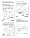
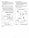
NOTE: Be sure the lift release cable's plastic covering
stays inserted into the trigger assembly for the next step
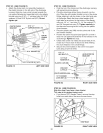
STEP 49: (SEE FIGURE 48)
* Push tbe lift handle down into the locked position.
Insert the end of the cable wire into the hole in the
lift rod Place the threaded fitting into the slot in the
lift bracket, with one bex nut above and one hex nut
a_d the _ockwasher below the s_ot.Tighten the nuts,
adjusting them to eliminate slack in the cable wire.
Refer also to the Service and Adjustments section on
page 29 in this manual.
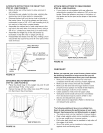
HINT: For easier assembly of the lift release cable, tilt the
snow thrower forward onto the spiral auger
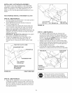
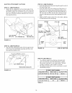
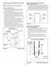
STEP 50: (SEE FIGURE 49)
• Tilt the snow thrower back down to the ground
• Remove the nylon tie which fastens the auger
drive belt to the discharge housing, leaving the belt
assembled around the pulleys.
• Remove the nylon tie which fastens the chute c_ank
rod to the crank rod support tube.
• Assemble the crank rod support tube to the bracket
on the left side of the discharge housing using two
5/16" x 1-1/4" carriage bolts (M), and 5/16" Nylock
nuts (CO).
DISCHARGE _ ,
', X,
HOUSING , \
• • CRANK ROD
5t16" NYLOCK NUT (CC) .SUPPORT TUBE
FIGURE 49
LEFT SIDE ViEW
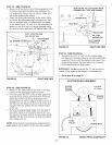
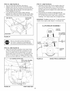
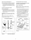
STEP 51: (SEE FIGURE 50)
* Attach the chute tilt control assembly to the top side
ot the crank support tube using two 5/16" x 1-3/4"
carriage bolts (L), bowed washers (Y) and 5/16"
Nylock nuts (CC).
LIFT RELEASE
_/-- " _._HEXNUT
TRIGGER _ _,
ASSEMBLY [ _
I \ _ WASBER
] / i HEXRDT
/\ CABLE
.... _;
CHUTE CRANK ROD "_
CRANK SUPPORT TUBE _
TILT CONTROL HANDLE ----="-_
,, _ TILT
5/16" _ 1-3/4 _ CONTROL
CARRIAGE BOL ASSEMBLY
BOWEDWASHER{Y) _ "_
5/16" NYLOCK NUT f,CC) /
FIGURE 50 LEFT SIDEVIEW
FIGURE 48 RIGHT SIDE VIEW
21