


9
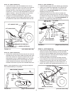
FIGURE 18 (Right Hand Side View)
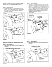
STEP 16: (SEE FIGURE 16)
• Assemble ball end of control cable up through hole in
cable end fi tting and pull until ball slips inside curled
edge of fi tting. If ball won't slip under edge of curl, it
will need to be inserted through open end of curl.
•
Assemble 1/4" x 1-1/2" (B) hex bolt down through the
cable end fi tting, the 5/8" long spacer (T) and the left
hand hole in the channel assembly. Secure with a
1/4" nylock nut (J).
Tighten.
NOTE:
Make sure the cable mount bracket is aligned
with the cable end fi tting to prevent binding of cable. The
other end of the control cable will be at tached in a later
step.
FIGURE 16 (Left Hand Side View)
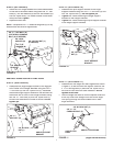
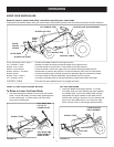
STEP 17: (SEE FIGURE 17)
• To attach the blade to the channel assembly, align
the notched holes in the pivot plate with the notched
holes in the blade. Insert a 1/8" x 1-1/4" cotter pin (P)
down through the hole at the bend in the blade pivot
shaft. Spread the ends of the pin. From the left side
insert the blade pivot shaft, bend facing top of blade,
through the notched holes. Secure the shaft with
another 1/8" x 1-1/4" cotter pin (P) through the end
hole in the shaft. Spread the ends of the pin.
• Remove the plastic cap and one 3/8" hex nut from the
bolt in the blade adjust spring. Adjust the re main ing
3/8" hex nut down approximately 1" onto the bolt
threads. Hook the spring over the spring mount rod.
Place the bolt up through the hole in the top edge of
the blade and reassemble the other 3/8" hex nut to
the bolt and tighten down against the top edge of the
blade. Re place the plastic cap over the end of the bolt
threads.
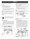
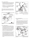
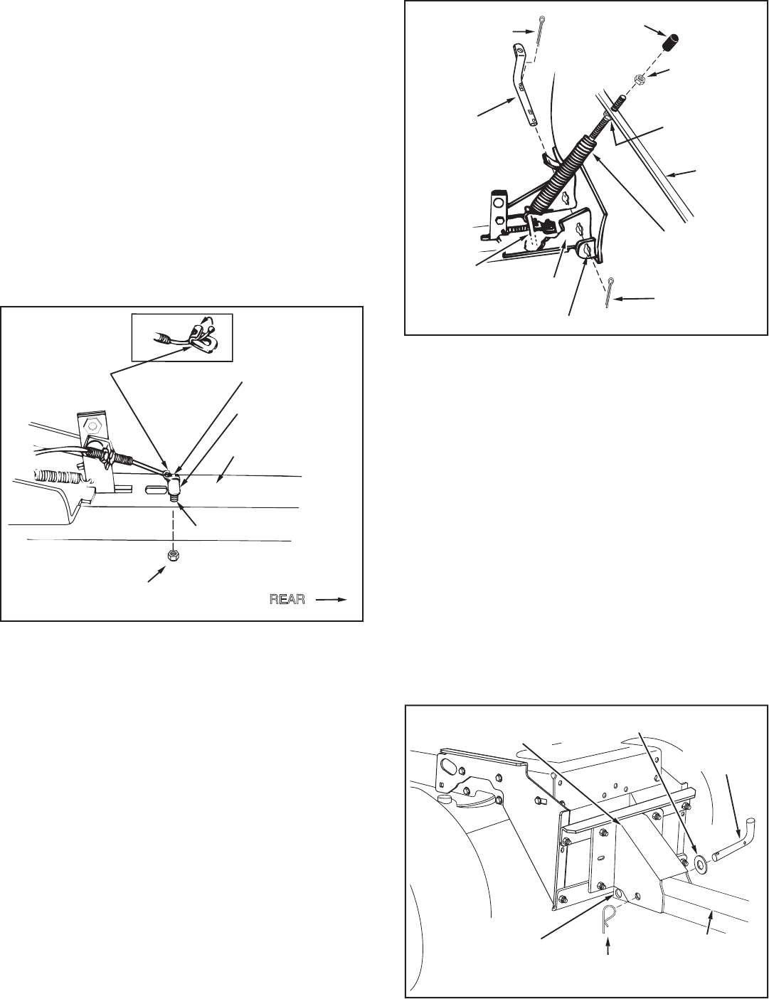
STEP 18: (SEE FIGURE 18)
• Assemble the large 1/2" washer (Q) onto the channel
pivot pin.
• Attach the chan nel as sem bly to the tractor by placing
the end of the chan nel as sem bly up inside the pivot
support brack et on the tractor. Align the hole in the
pivot support bracket with the second hole from the
end in the channel assembly. Insert the channel pivot
pin through the aligned holes from the left side and
secure with a hairpin cotter (O).
(Right Hand Side View)
FIGURE 17
3/8" HEX NUT
(TOP)
PLASTIC
CAP
3/8" HEX NUT
(BOTTOM)
BLADE
1/8" x 1-1/4"
COTTER PIN (P)
BLADE
PIVOT
SHAFT
SPRING
MOUNT
ROD
BLADE
ADJUST
SPRING
1/8" x 1-1/4"
COTTER PIN (P)
PIVOT PLATE
NOTCHED HOLE
HAIRPIN
COTTER (O)
PIVOT SUPPORT
BRACKET
CHANNEL
PIVOT PIN
CHANNEL
ASSEMBLY
1/2" WASHER (Q)
CHANNEL
ASSEMBLY
HOLE
1/4" x 1-1/2"
HEX BOLT (B)
CABLE END
FITTING
1/4" NYLOCK
NUT (J)
5/8" SPACER (T)
CHANNEL
ASSEMBLY
HOLE
REAR