4
K
M
J
ASSEMBLY
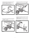
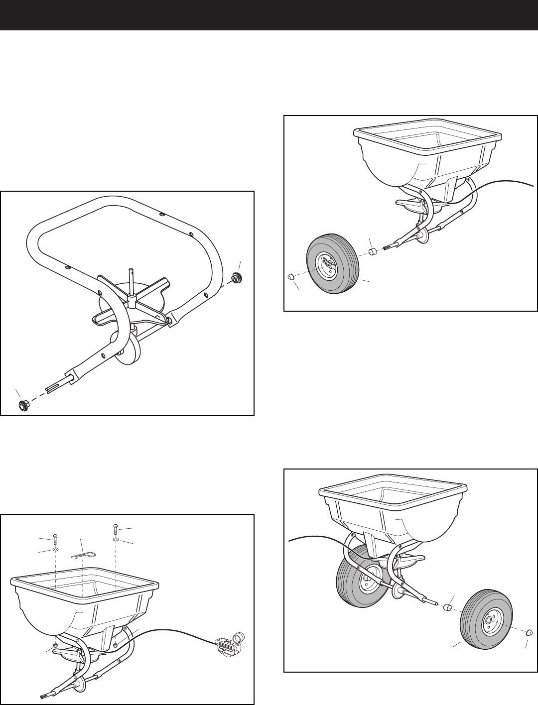
FIGURE 1
FIGURE 2
FIGURE 4
FIGURE 3
TOOLS REQUIRED FOR ASSEMBLY
(2) 7/16" Wrenches
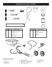
• Remove all parts and hardware packages from the
carton. Lay out all parts and hardware and identify
using the illustrations on page 3.
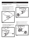
• Insert each side of the axle of the impeller assembly
into the frame tube. See gure 1.
• Insert the two hex ange bearings (I) into the frame
tube. See gure 1.
• Attach the hopper to the frame tube using two 1/4" x
1-1/2" hex bolts (A), 1/4" washers (G), and 1/4" nylock
nuts (D) as shown in gure 2. Tighten.
• Insert an 1/8" hair cotter pin (E) into the hole at the
top of the impeller. See gure 2.
• Slide a spacer (J) over the right side of the axle. See
gure 3.
• Attach the drive wheel (9) to the right (indented) side
of the axle. Secure the wheel in place with a hub cap
(K). See gure 3.
I
I
D
D
A
A
H
H
E
9
K
N
J
10
• Slide a spacer (J) over the left side of the axle. See
gure 4.
• Attach the wheel (10) to the left side of the axle.
Secure the wheel in place with a hub cap (K). See
gure 4.


