


7
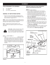
FIGURE 7
ORIGINAL BOLT
OR BOLT (E) AND
WASHER (H)
SPRING
ADJUST
TO FIT
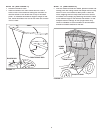
FIGURE 10
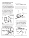
FIGURE 9
5/16" x 2"
CARRIAGE BOLT (B)
5/16" FLAT
WASHER (H)
PLASTIC
KNOB (L)
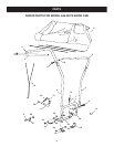
STEP 9:
(SEE FIGURE 10)
• Assemble the top tubes to the upright tubes using
two 1/4" x 1-1/2" hex bolts (D) (outside) and two 1/4"
nylock nuts (F) (inside).
Do not tighten yet.
• Fit the front U-tube onto the top tubes. Fasten the
tubes together using two 1/4" x 1-1/2" hex bolts
(D) (outside) and two 1/4" nylock nuts (F) (inside).
Tight en all
loose bolts and nuts.
• Fit the three support rods into the holes in the top
tubes, with the rods arching upward.
Do not
over
bend the rods when installing.
1/4" NYLOCK
NUT (F)
U-TUBE
1/4" x 1-1/2"
HEX BOLT (D)
SUPPORT ROD
1/4" x 1-1/2"
HEX BOLT (D)
1/4" NYLOCK
NUT (F)
TOP TUBES
STEP 7:
(SEE FIGURE 7 AND 8)
• Raise the tractor seat and remove the springs and
bolts from the rear fender using a 1/2" socket for GT
tractors or a 9/16" socket for LT tractors.
• Place the base tube assembly onto the rear fender.
Align the front or rear slot in the base brackets with
the spring mounting holes. Check for clearance with
the seat lowered and the rear bagger (optional)
attached. If needed, reposition the base brackets to a
different set of holes in the base tubes.
• If the base leg tubes rub against the fender, attach the
adhesive pads (K) to the bottom of the base leg tubes.
• Attach the seat springs and the base brackets to the
rea
r fender using the spring bolts that you removed.
On GT tractors, if the spring bolts were less than 1"
long, use the 5/16" x 1" bolts (E) and 5/16" washers
(H) supplied with the Snow Cab. Align the base leg
tubes on the rear fender. Use a 1/2" socket (GT) or
a 9/16" socket (LT) to tighten the seat spring bolts
using
moderate force
.
Do not ov
ertighten. Next,
tighten the bolts fastening the base leg tubes to the
base brackets.
COMPLETING ASSEMBLY - ALL TRACTORS
STEP 8:
(SEE FIGURE 9)
• Assemble the upright tubes to the base assembly
using a 5/16-18 x 2" carriage bolt (B), 5/16" fl at
washer (H) and plastic knob (L) for each tube.
NOTE:
If holes are diffi cult to align, loosen bolts attaching
base tubes to mounting bracket. If hole alignment is still
diffi cult, loosen bolts attaching mounting bracket to rear
fender. Retighten all bolts when fi nished.
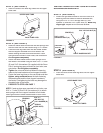
FIGURE 8
5/16" X 2"
CARRIAGE BOLT (B)
5/16" NYLOCK NUT (G)
REAR SUPPORT BRACKET
ADHESIVE PAD (K)
If the base tubes do not rest down against the fender:
• Attach an adhesive pad (K) to bottom of each rear
support bracket. Attach the brackets to appropriate
holes in base support tubes using two 5/16" x 2"
carriage bolts (B) and 5/16" nylock nuts (G). Adjust
brackets to support the base tubes, then
tighten
.