


5
ASSEMBLY
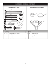
TOOLS REQUIRED FOR ASSEMBLY
(2) 7/16" Wrenches
(2) 1/2" Wrench
(1) 1/2" or 9/16" Socket Wrench
REMOVAL OF PARTS FROM CARTON
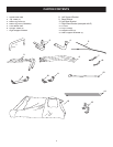
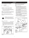
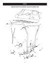
FIGURE 2
5/16" x 2"
CARRIAGE BOLT (B)
5/16" x 2"
HEX BOLT (C)
5/16" NYLOCK NUT (G)
1/4" NYLOCK
NUT (F)
1/4" x 1"
CARRIAGE BOLT (I)
5/16" NYLOCK
NUT (G)
BASE BRACKET
LEFT
SUPPORT
BRACKET
RIGHT
SUPPORT
BRACKET
BASE LEG TUBE
(FLATTENED)
BASE LEG TUBE
THIS HOLE
IS HIGHER
SHORT END
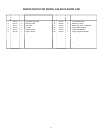
• Remove all parts and hardware packages from the
carton. Lay out parts and hardware and identify using
the illustrations on pages 3 and 4.
NOTE:
Not all of the supplied parts and hardware will be
needed for one particular tractor. Unneeded items may be
discarded after assembly has been completed.
NOTE:
Right hand (RH) and left hand (LH) are
determined from the operator
's position while seated on
the tractor.
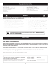
CAUTION:
Make sure tractor seat raises
and lowers freely after attaching Snow
Cab. The tractor's operator presence safety
switch will not operate if seat is stuck down.
STEP 1:
(SEE FIGURE 1)
•
Look
under the front of your tractor
Look under the front of your tractorLook
. I
f there is a single
mower deck suspen
sion bracket located
underneath
the mi
dd
le of the front axle, continue
on to step
2
. I
f
yo
ur tractor does not have a mower deck susp
ension
bracket
underneath the mi
dd
le of the front axle
, skip
to step 5 on page
6 for tractors with dual suspension
brackets.
MOWER DECK
SUSPENSION
BRACKET
FIGURE 1
INSTRUCTIONS FOR TRACTORS WITH
SINGLE SUSPENSION BRACKET
STEP 2:
(SEE FIGURE 2)
• The four holes in the base bracket are unequal in
height. Place the base bracket on a fl at surface with
the holes that are higher facing away from you.
• Attach the right side of the base bracket to the front
two holes in the fl attened base leg tube using two
5/16" x 2" carriage bolts (B) and 5/16" nylock nuts (G).
Make only fi nger tight.
• Attach the left side of the base bracket to the fourth
and fi fth holes in one of the base leg tubes using two
5/16" x 2" carriage bolts (B) and 5/16" nylock nuts (G).
Make only fi nger tight.
• Attach the long end of the right support bracket to the
outside of the fl attened end of the right base leg tube
using a 1/4" x 1" carriage bolt (I) and 1/4" nylock nut
(F).
Make only fi nger tight.
• Attach the left support bracket to the outside of the left
base leg tube using one 5/16" x 2" hex bolt (C) and
5/16" nylock nut (G).
Make only fi nger tight
.