6
Call 1-866-576-8388 for missing parts or assembly help
DO NOT RETURN TO STORE
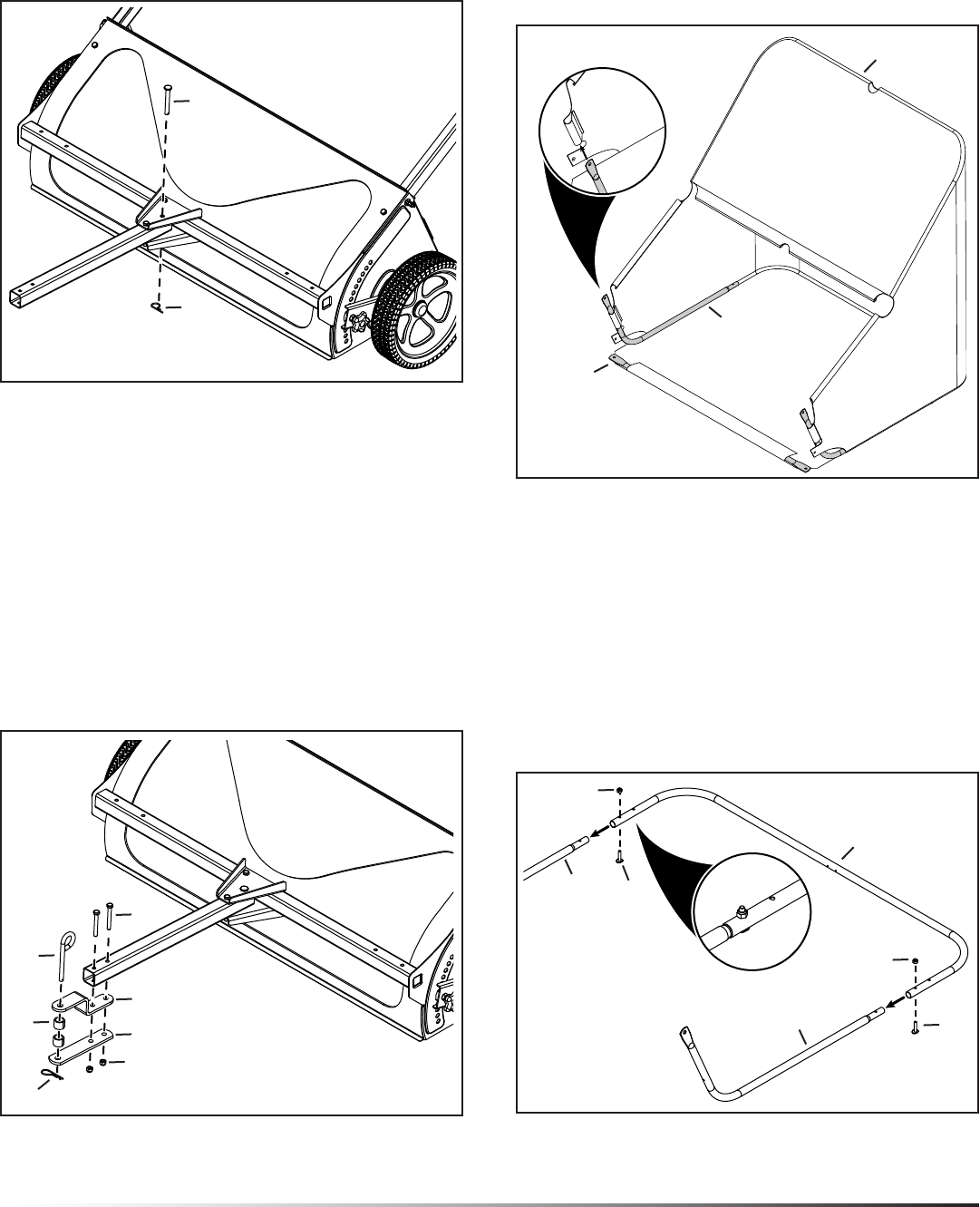
FIGURE 5
20
19
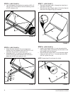
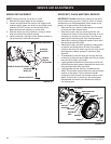
STEP 5: (SEE FIGURE 5)
Lock the drawbar into position by inserting a 3/8" x 3" •
hitch pin (20) into the center hole and securing it with
a 3/32" cotter pin (19).
FIGURE 6
STEP 6: (SEE FIGURE 6)
Attach the hitch bracket (12) and straight hitch •
bracket (13) to the drawbar using two 5/16" x 2-1/2"
hex bolts (15) and 5/16" nylock nuts (21).
Assemble a 3/8" x 3" hitch pin (35) and two 3/4" •
spacers (22) to the hitch brackets. Secure them in
place with a 3/32" hair cotter pin (18).
21
13
12
15
35
22
18
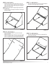
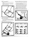
STEP 7: (SEE FIGURE 7)
Slidethebagframetube(1)throughthefrontapin•
the bottom of the bag.
Slidethetwolowerhoppertubes(10)intotheapsat•
the front of the hopper bag (3) as shown.
FIGURE 8
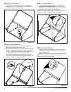
STEP 8: (SEE FIGURE 8)
Install a rear hopper tube (11) onto the ends of the •
lower hopper tubes (10) making sure the holes in the
rear hopper tube are facing up.
Secure the rear hopper tube (11) to the lower hopper •
tubes (10) with two 1/4" x 1" curved head bolts (26)
and 1/4" nylock nuts (24).
NOTE: Hopper bag (3) not shown for clarity.
24
24
11
10
10
26
26
FIGURE 7
3
10
1


