


5
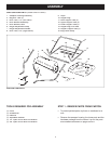
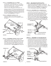
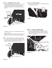
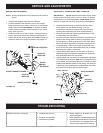
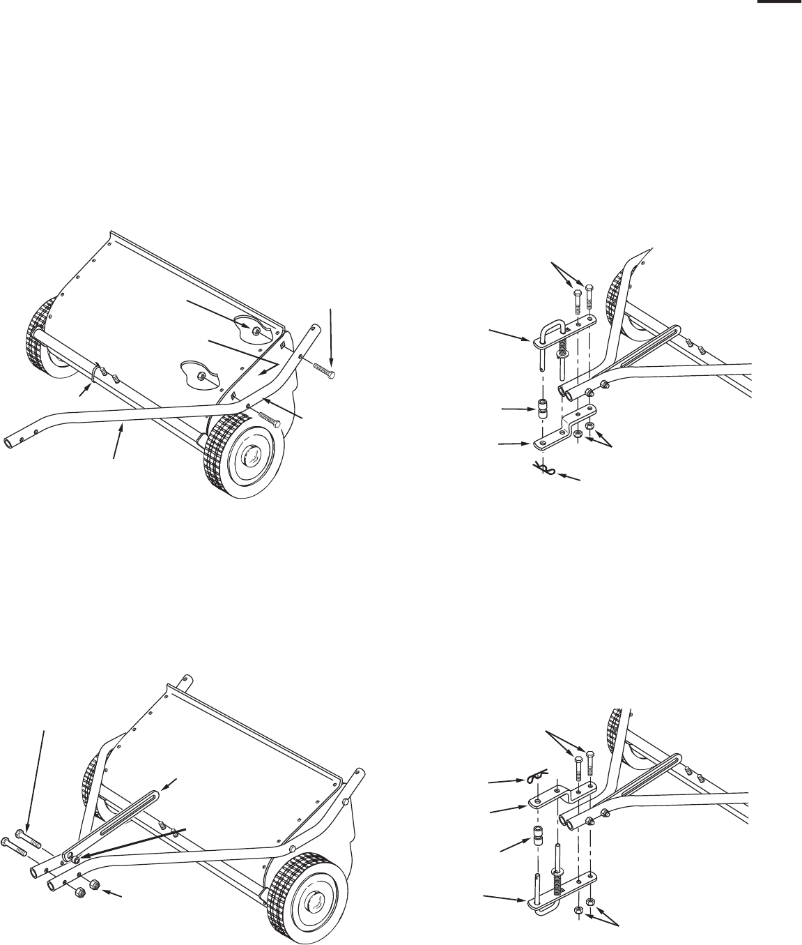
STEP 4 - ASSEMBLE HEIGHT ADJ. STRAP
•
Place the spacer bushing (I) into the hole in the
height adjustment strap. Place the strap and bushing
between the hitch tubes, aligning them with the rear
hole. Fasten the hitch tubes together, with the strap
and bushing between them, using two hex bolts (A)
and nylock nuts (E).
Do not tighten yet.
See fi gure 2.
FIGURE 1
FIGURE 2
FIGURE 3
STEP 5 - MEASURE TRACTOR HITCH
•
Use the mark beside this paragraph to measure the
height of the tractor hitch. The mark is 10" from the
bottom of the page. If the tractor hitch is less than 10"
above the ground, go to
STEP 6a
. If the tractor hitch
is 10" or more above the ground, go to
STEP 6b
.
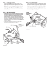
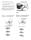
STEP 6a - ASSEMBLE HITCH BRACKETS
•
If the tractor hitch is less than 10" above the ground,
place the bent hitch bracket underneath the hitch
tubes and place the hitch bracket assembly on top of
the hitch tubes. Insert two hex bolts (B) through the
brackets, with the rear hex bolt between the cross
bolts in the hitch tubes. Secure the hex bolts (B) with
two nylock nuts (E). See fi gure 3.
Do not tighten yet.
•
Assemble the two spacers (J) onto the hitch pin and
secure the pin with the hairpin cotter (K). See fi gure 3.
FIGURE 4
HEX BOLT (A)
NYLOCK NUT (E)
SPACER
BUSHING (I)
HEIGHT
ADJUSTMENT
STRAP
NYLOCK NUTS (E)
HITCH BRACKET
ASSEMBLY
BENT HITCH
BRACKET
HEX BOLTS (B)
HAIRPIN COTTER (K)
SPACERS (J)
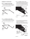
STEP 6b - ASSEMBLE HITCH BRACKETS
•
If the tractor hitch is 10" or more above the ground,
place the bent hitch bracket on top of the hitch tubes
and place the hitch bracket assembly underneath
the hitch tubes. Insert two hex bolts (B) through the
brackets, with the rear hex bolt between the cross
bolts in the hitch tubes. Secure the hex bolts (B) with
two nylock nuts (E). See fi gure 4.
Do not tighten yet.
•
Assemble the two spacers (J) onto the hitch pin and
secure the pin with the hairpin cotter (K). See fi gure 4.
NYLOCK NUTS (E)
BENT HITCH
BRACKET
HITCH BRACKET
ASSEMBLY
HEX BOLTS (B)
SPACERS (J)
HAIRPIN
COTTER (K)
10"
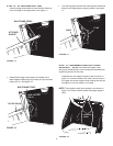
HEX BOLT (C)
HITCH TUBE (L.H.)
PLASTIC TIE
NYLOCK NUT (E)
TUBE
MARKED
“77L”
HOUSING
MARKED “L”
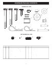
STEP 2 - ASSEMBLE HITCH TUBES
•
The hitch tubes are stamped with a "77
L
" for the
left tube and a "76
R
" for the right tube. The sweeper
housing is marked with and "
L
" on the left with side
and an "
R
" on the right side. See fi gure 1.
•
Hold the left hitch tube against the left side of the
sweeper so that the "77
L
" on the tube faces away from
the sweeper. Attach the hitch tube using two hex bolts
(C) and nylock nuts (E). Repeat for the right hitch tube,
but with the "76
R
" facing in toward the right side of the
sweeper.
Do not tighten yet.
See fi gure 1.
STEP 3 - REMOVE PLASTIC TIE
•
Remove the plastic tie that fastens the height
adjustment tube to the front of the sweeper housing.
See fi gure 1.