


ASSEMBLY
A. PREPARATION
Your Operator's Manual has been developed to help
you assemble the unit and to understand its safe opera-
tion. It is important that you read your manual com-
pletely to become familiar with the unit before you begin
assembly.
I. READ YOUR OPERATOR'S MANUAL.
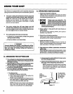
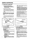
2. Tools you will need:
a:
/
Z" 1-1/4inch Wrench
7116inch Wrench "
3/8 inch Wrench
or
Z
Adjustable Wrench
b. _ _
_ Slotted Screwdriver
CLAMP ___J ._
DRIVE SHAFT _ _
.o'ovo
Figure 1
ASSEMBLYSTEPS
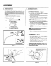
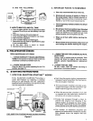
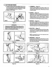
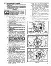
1. DRIVE SHAFT HOUSING -- Figure 1.
a. Place clamp from loose parts bag on the engine
shroud as shown inFigure 1.
b. Pull about 6 inches oftheflexible drive shaft out from
the drive shaft housing.
c. Fitthe end of the flexible drive shaft intothe square-
shaped opening insidethe engine shroud. Figure 1.
NOTE: Turnthe engine as necessarytoline upparts.
d. Align the groove in the drive shaft housing with the
key inside the engine shroud opening.
e. Firmly push the drive shaft housing straight into the"
engine shroud until it bottoms out (about 1-1/2
inches).
f. Install clamp screw and square nut as shown in
Figure 1.
NOTE: The nutmust be mountedon the tab side of
the clamp to keep nut from turning.
g. Tighten the clamp screwsecu rerywith a screwdriver.
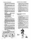
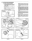
2. CUTTING HEAD -- Figure 2
a. Holdthe dust cup with a 1-1/4"wrench tokeep the
dust cup fromturning. Figure 2.
b. Thread the cutting head clockwise onto the arbor
shaft, against the dust cup, and as tight as possible
with your hand. Figure 2.
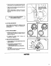
c. Press the tap button and pull the cutting linefrom the
head a minimum of 2 inches. Figure 3.
L.
NOTE: Toremove the cu_ing bead, hold the dust cup
.... with at-l/4"-wrench and unthread the cutting head
counterclockwise &[_,_ .
1-1/4"
WRENCH
DI RECTI ON
TO INSTALL
ARBOR SHAFT
DUST CUP
Figure 2
Approximately2 inchesof line
canbe advanced each time the
Figure 3