


21
Carburetor
WARNING: If any adjustments are made
to the engine while the engine is running
(e.g. carburetor), keep clear of all
moving parts. Be careful of heated
surfaces and mufflers.
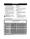
Minor carburetor adjustments may be required to
compensate for differences in fuel temperature,
altitude and load.
Service
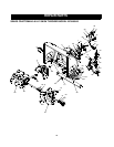
Augers
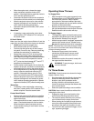
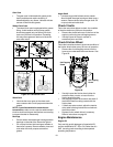
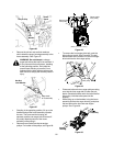
The augers are secured to the spiral shaft with two
shear bolts and hex lock nuts. See Figure 23. If you
hit a foreign object or ice jam, the snow thrower is
designed so that the bolts will shear. This type of
boltt is used where vibration occurs.
If the augers do not turn, check to see if the bolts
have sheared. Two replacement shear bolts (shown
in Figure 23 inset ) and hex lock nuts have been
provided with the snow thrower. Since lock nuts
cannot be threaded onto a bolt by hand, use a
wrench. When replacing bolts, spray an oil lubricant
into shaft before inserting new bolts.
Figure 23
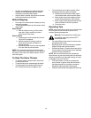
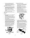
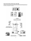
Shave Plate and Skid Shoes
The shave plate and skid shoes on the bottom of the
snow thrower are subject to wear. They should be
checked periodically and replaced when necessary.
• Remove the six carriage bolts, belleville
washers and hex nuts which attach skid shoes
to the snow thrower on two sides. See Figure 17.
• Reassemble new skid shoes with the six
carriage bolts, belleville washers (cupped side
goes against skid shoes) and hex nuts. Make
certain the skid shoes are adjusted to be level.
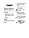
• To remove shave plate, remove the skid shoe
first. Next remove carriage bolts, belleville
washers and hex nuts which attach shave plate
to the snow thrower housing. For location of
shave plate, see Figure 24.
Shear Bolt
Hex Lock
Nut
AugerAuger
• Reassemble new shave plate, making sure
heads of the carriage bolts are to the inside of
the housing. See Figure 24. Reinstall skid shoe.
Tighten all hardware securely.
Figure 24
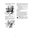
Replacing Belt
WARNING
: Disconnect the spark plug
wire from the spark plug and ground.
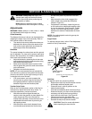
Auger Belts
• Remove the plastic belt cover on the front of the
engine by removing the two self-tapping screws.
See Figure 25.
Figure 25
• Disconnect chute crank assembly at the
discharge chute by removing the hairpin clip and
the two flat washers. See Figure 26.
Carriage Bolt Carriage Bolt
Hex Nut
Washer
Washer
Washer
Self-Tapping
Screw
Engine
Auger Housing
Belt Cover
Self-Tapping
Screw