


18
SERVICE AND MAINTENANCE
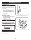
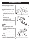
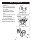
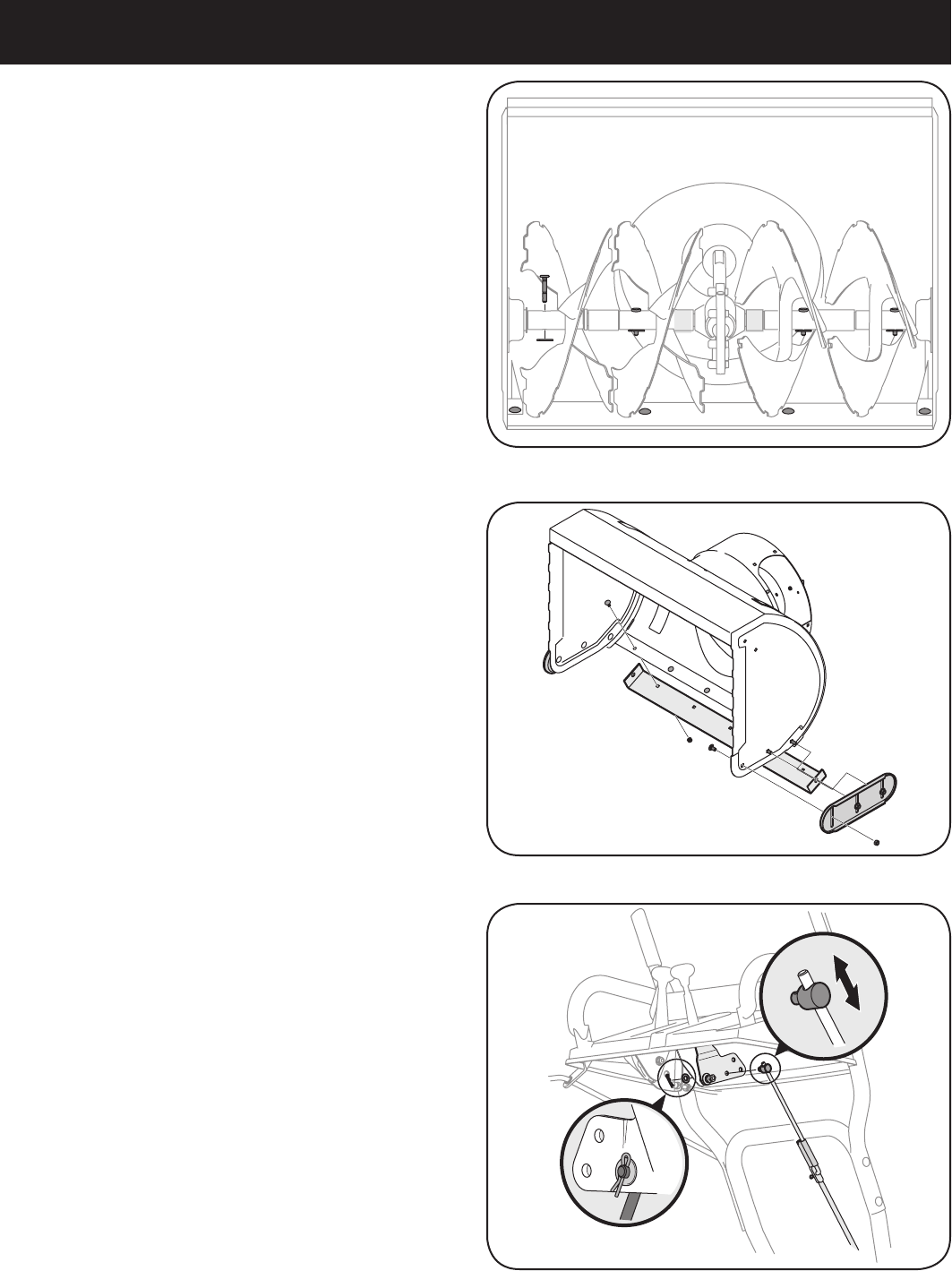
Auger Shaft
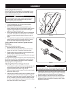
At least once a season, remove the shear pins on auger shaft. Spray
lubricant inside shaft, and around the spacers and flange bearings
found at either end of the shaft. See Figure 18.
SHAVE PLATE AND SKID SHOES
The shave plate and skid shoes on the bottom of the snow thrower are
subject to wear. They should be checked periodically and replaced
when necessary.
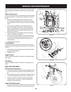
Skid Shoes
NOTE: The skid shoes on this machine have two wear edges. When
one side wears out, they can be rotated 180° to use the other edge.
Remove the six carriage bolts and hex nuts that secure the two 1.
skid shoes to the sides of the auger housing. Refer to Figure 19.
Position the new skid shoes and secure with the carriage bolts 2.
and hex nuts. Make certain the skid shoes are adjusted to be
level.
Shave Plate
Remove the hex nuts and carriage bolts that secure the shave 1.
plate to the bottom of the housing.
Remove the rear most hex nut and carriage bolt securing the back 2.
of each skid shoe to the sides of the housing. Loosen the four
remaining hex nuts securing the skid shoes.
Slide the shave plate out of the off-set slot at the bottom of the 3.
housing, and from between the skid shoes and side panels of the
housing.
With the mounting holes toward the back of the unit, slide the new 4.
shave plate into position and secure with the fasteners removed
previously.
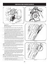
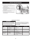
ADJUSTMENTS
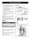
Shift Rod
If the full range of speeds (forward and reverse) cannot be achieved,
refer to Figure 20 to the left and adjust the shift rod as follows:
Looking underneath the handle panel, note which of the three 1.
holes in the shift lever the ferrule is inserted into. Also note the
direction of insertion. Then remove the internal cotter pin and flat
washer from the ferrule and withdraw the ferrule from the shift
lever. See Figure 20.
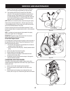
Place shift lever in sixth (6) position or fastest forward speed.2.
Push shift rod and shift arm assembly down sharply as far as it 3.
will go to put the drive into the fastest forward position.
As necessary, rotate the ferrule up or down the shift rod until the 4.
ferrule lines up with the hole from which it was earlier removed.
See Figure 20.
From the direction noted earlier, insert the ferrule into the proper hole. 5.
Reinstall the washer and the internal cotter pin.6.
Chute Control
The distance snow is thrown can be adjusted by adjusting the angle of
the chute assembly. Refer to the Operation section for instructions.
The remote chute control cables have been pre-adjusted at the factory.
Figure 19
Figure 20
Figure 18