


spider fails completely,you willexperience a loss of
power.
,_ WARNING: Never hit the engine shaft in
any manner, as a blow will cause permanent
damage to the engine or the pump.
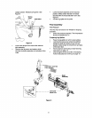
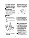
Follow the instructions carefully as the alignment of
the couplings is critical.
• Disconnect the spark plug wire from the spark
plug, and keep it away from the spark plug.
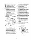
• Using a 1/2 inch wrench, remove three nuts and
lock washers which secure the pump to the
coupling shield. Two nuts are at the bottom
corners and one is in the top center. See Figure
17. Remove the pump.
• Remove the nylon spider insert from the
coupling and inspectfor wear. Replace if
necessary.
• Inspect the engine coupling half jaws for signs of
wear. Replace if necessary.
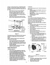
Coupling Shield Rear Coupling
\ Support Bracket
Lock
Washer
Hex
Nut
?p
Coupling 1
Half ock
Washer
Figure 17
To replace engine coupling half: Rotate the
engine by pullingstarter handle until engine
couplinghalf set screw isat bottom. Loosen set
screw using 1/8 inch allenwrench. Slide
couplinghalf offengine shaft. See Figure 17.
Installnew couplinghalfon engine shaft making
sure to align key way in couplinghalf with key in
the engine shaft.
Slidecoupler half along engine shaftuntilthe
end ofthe shaft isflush withthe inner portionof
the coupling half.(There must be space
between end ofthe engine support bracket and
the coupling half.) Apply LoctiteTM tothreads of
set screw and torque to 78 inch-pounds.
• Inspect the pump coupling half jaws for signs of
wear. Replace ifnecessary.
To replace pump coupling half: Loosen set
screw using 1/8 inchalien wrench. Slide
couplinghalfoff pumpshaft.
Installnew couplinghalf on pump shaftmaking
sure to align key way in couplinghalf with key in
pump shaft. Rotate couplinghalf untilset screw
faces down. Do nottighten set screwnow.
• Install new spider inserton to the engine
couplinghalf.
• Align pump couplinghalf with nylon"spider" by
rotating engine usingstarter handle.
Slide couplinghalf intoplace whileguidingthree
mountingbolts through holes in pump support
bracket.
Note: The pump couplinghaff can be rotated by hand
toaid in alignment. If the twoparts are not aligned
nght, the unitwill not operateproperly and damage
could occur.
• Secure with nutsand washers removed earlier.
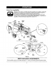
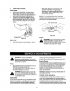
• Set .035 to .060 inch clearance between the
nylon "spider" and the engine coupling half by
sliding a matchbox cover between the nylon
"spider" and the engine coupling half and
moving pump coupling half as needed. See
Figure 18.
• Apply LoctiteTM to threads of set screw. Tighten
set screw to torque 78 inch-lbs. This should
secure the pump coupling half.
Reattach spark plug wire to spark plug.
PUMP
s,t 4
Clearance __lves
Figure lg
16