


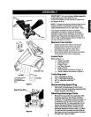

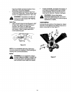
I Hex Nut
J
\
\
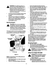
Step 1
Hinge
Discharge
Chute
Wing
Knob
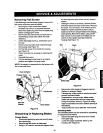
Figure 3
• Place second spacer over hex bolt insidethe
other part ofthe hinge as shown in the inset,
Secure tightly with hex lock nut.
• Secure bothsidesofdischargechuteto housing
usingwingknobsthatyou earlierremoved.This is
showninstep2 in Figure3.Tightenwing knobs.
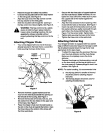
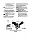
Attaching Hopper Assembly
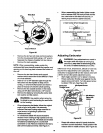
• Remove the 8-3/8" longhex bolt and the hex nut
from the bottom ofthe inlet guide opening. See
Figure 4 inset.
• Place the hopper assembly on the ground and
hold it in the position shownin Figure 4.
Inlet Gu de Opening
|0 ,
• Holdingthe hopper, push hopper pivotdoor
down inside the hopper. See Figure 4.
• Slidethe hopper assembly towards the chipper-
shredder housing sothat the upper guide on the
hopperassembly slides under the stop washer
on each side ofthe inletguide. See Figure 4.
• Alignthe two holes (one on each side) ofthe
lower hopper withthe two holes (one on each
side) of the inletguide. See. Figure4 inset.
• Insertthe hex bolt (that you eadier removed)
fromthe leftthrough the hole on the hopper _n_ °
the inletguide. Insertthe hex nutonto the bolt
from the other side. See Figure 4 inset.
• Tighten the bolttillthe lock nut isengaged. Make
sure to remove sideplay from the bolt, butthe
hoppershould be able to pivot.
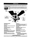
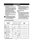
Figure 5
• To raise the hopper, holdthe hopper by the
hand-hold and liftit uptill itclicks intoposition.
See Figure 5.
• To Iowerthe hopper, hold the hopper bythe
hand-hold and pullthe release bar. The hopper
shoulddrop down. See Figure 5.
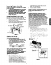
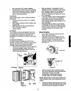
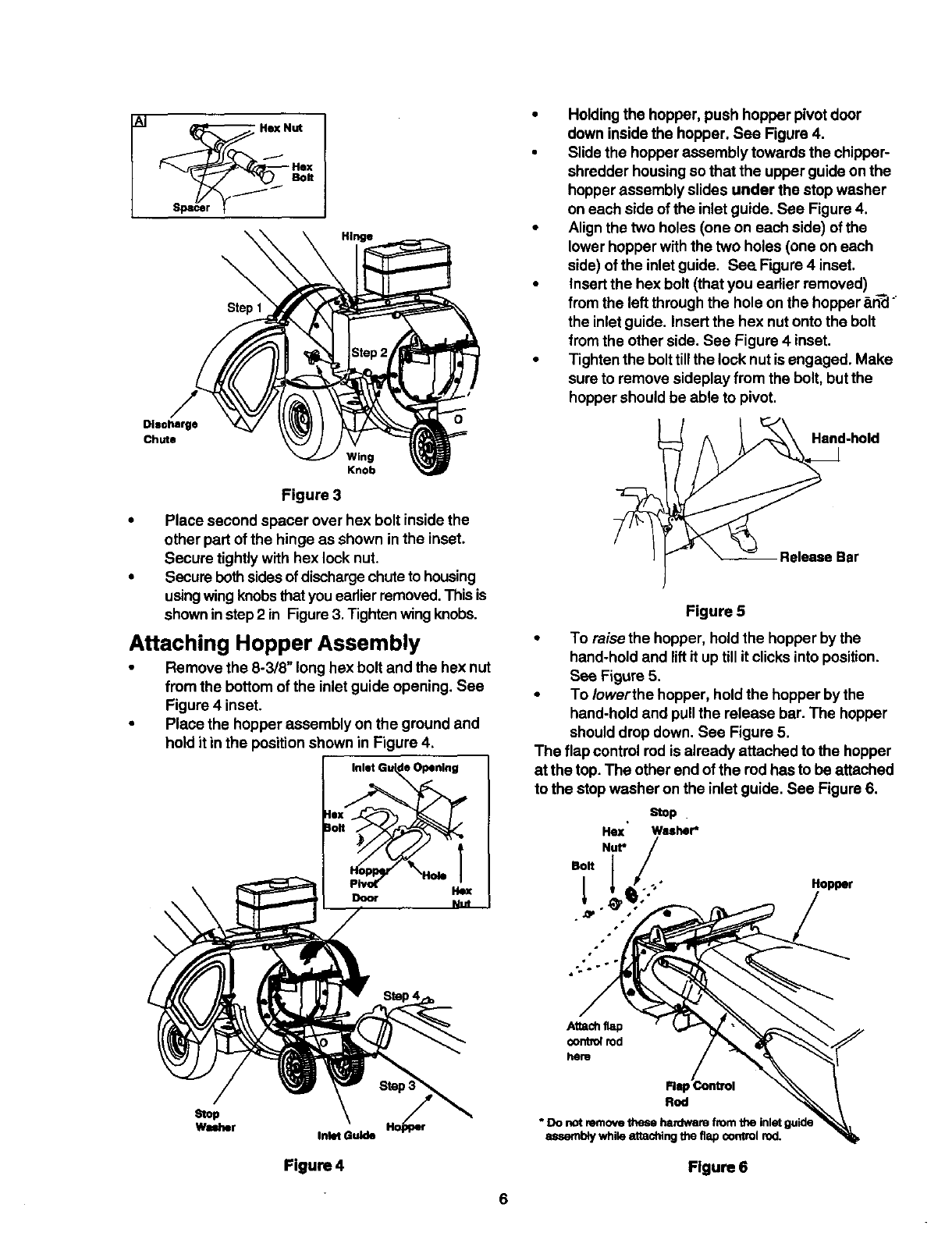
The flap controlrod isalready attached to the hopper
at the top.The other end ofthe rodhas to be attached
to the stop washer on the inlet guide. See Figure 6.
Stop .
He](' Washer*
Nut*
Bolt l
Hopper
Stop
Washer
Inlet Guide
Figure 4
Attachflap
control rod
hem
Fist
Rod
• Do not remove these hardware fromthe inletguide
mmernblywhile attachingthe flap control rod.
Flgure6