SHARPENINGORREPLACINGCHIPPER
BLADE
Because the engine on this unit has a tapered
crankshaft, a special impeller removal tool (part
number 753-0900) is required to remove the impeller
assembly. For further assistance, contact your Sears
Service Center.
NOTE: When tipping the unit, empty the fuel tank and
keep engine spark plug side up.
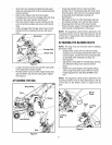
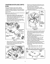
• Disconnect and ground the spark plug wire.
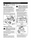
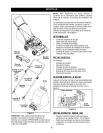
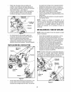
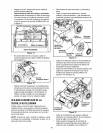
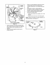
• Remove the front hubcaps, lock nuts, front
wheels, and wave washers that attach to the pivot
arm assemblies. See Figure 14.
• Remove the shoulder screws and bell washers
that go through the pivot arms and height bracket
adjusters to the front support brace.
Arm Assembly
Bell Washer
Washer
Ht
Height Adjustment
Bracket
Shoulder
Screw
Lock Nut
Figure 14
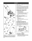
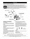
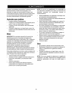
Remove the three screws on the upper housing
that secure the nozzle cover and the nine screws
that secure the lower housing to the upper
housing. See Figure 15.
Housing
Screw_
Lower Housing
Screws Screws
Figure 15
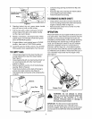
• Remove lock nut that secures flail screen to the
lower housing. The flail screen does not have to
be removed. Refer to Figure 12.
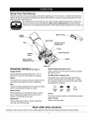
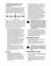
• Remove the hex bolt, lock washer, and flat
washer that secure the impeller assembly to the
crankshaft. See Figure 16.
Upper
Flail
Blade
BOTTOM VIEW
Figure 16
• Apply lubricant to the threads of impeller removal
tool and then thread the tool into the crankshaft.
Stop when the impeller assembly can move on
the crankshaft.
• Remove the impeller assembly from the
crankshaft. Unthread the impeller removal tool
from the impeller assembly.
• Remove the chipper blade using a 3/16" allen
wrench on the outside of the blade and 1/2"
wrench on the underside of impeller assembly.
• Replace or sharpen chipper blade.
• When sharpening blade, protect hands by using
gloves and follow the original angle of grind.
• Reassemble by performing the previous steps in
reverse order.
• Tighten blade screws to 210 - 250 in-lbs.
• Tighten impeller bolt to 375 - 425 in-lbs.
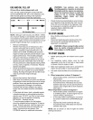
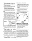
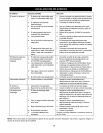
NOTE: Make certain chipper blade is reassembled
with the sharp edge facing upward. See Figure 17.
Fl_:, _Chipper
.... BI
- _ _ _lmpeller
_1] _ Assembly
Figure 17
13