


6
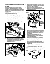
• Secure the two handles by tightening the upper
wing nuts (carriage bolts must be seated properly
into the handle).
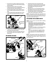
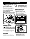
• Remove the hairpin clips from the handle
brackets and remove the carriage bolts and wing
nuts from the lower handle. See Figure 3.
• Place the bottom holes in lower handle over the
pins on handle brackets and secure with hairpin
clips.
• Insert carriage bolts through upper hole in lower
handle from the outside and secure with wing
nuts.
Figure 3
• Loosen the wing nut that secures the rope guide
to the right side of upper handle.
• Pull the starter rope out of the engine slowly and
slip the starter rope into the rope guide. Tighten
the wing nut.
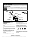
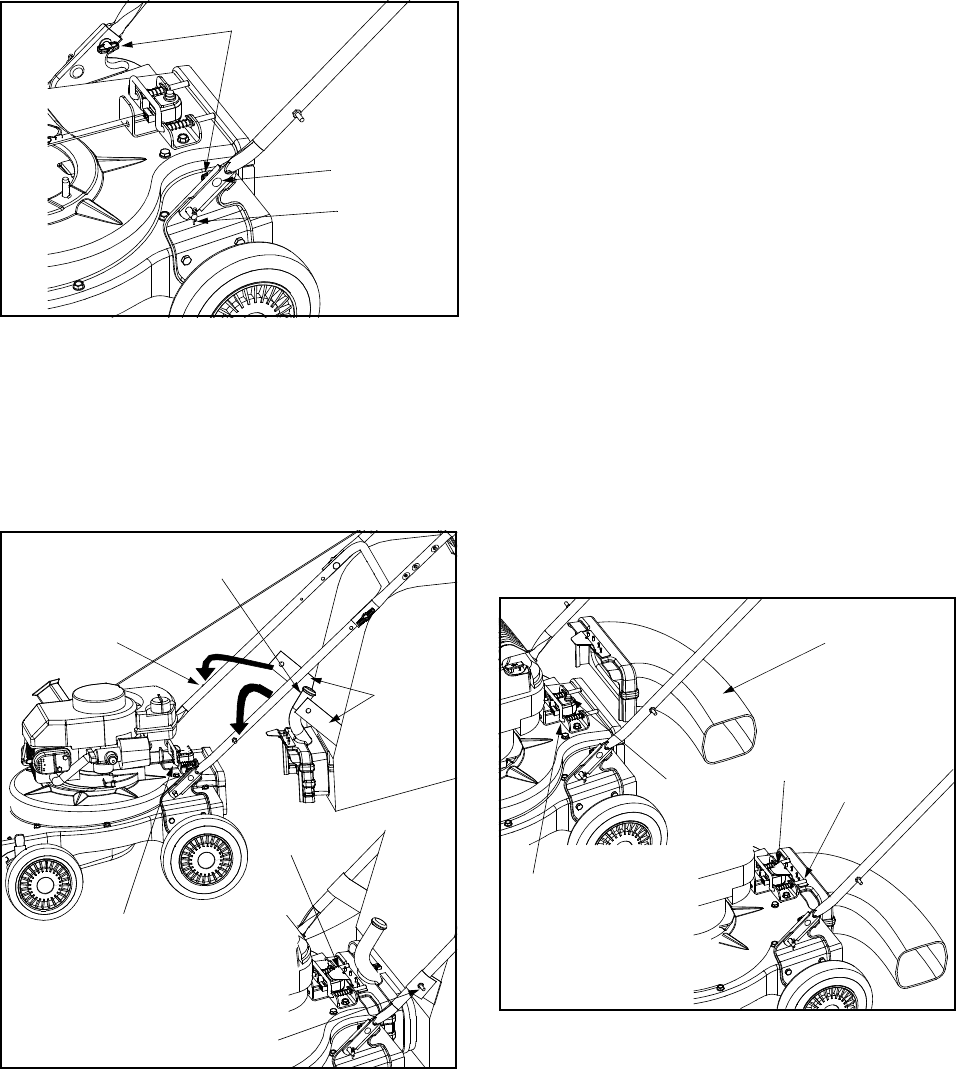
ATTACHING THE BAG
Figure 4
Wing Nuts
Carriage Bolt
Hairpin Clip
Bag Handle
Straps
Stud
Front Tab
Stud
Locking Rod
• Grasp bag handle with one hand and slide
locking rod on mounting bracket with other hand
toward engine. Use the end of mounting bracket
as leverage when sliding the locking rod.
See Figure 4.
• Slip bag over the rim of the discharge opening
and release locking rod to secure bag in place.
• Snap bag clip to the top of the lower handle.
• Place the lower straps on the bag over the top of
lower handle, hooking them on the studs.
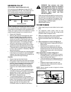
NOTE: The bag/chute switch button attached to the
mounting bracket must be fully depressed by the tip
of front tab on bag handle when securing the bag or
engine will not start. See Figure 5.
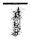
ATTACHING THE BLOWER CHUTE
NOTE: The bag must be removed before installing
the blower chute.
• Grasp blower chute with one hand and slide
locking rod on mounting bracket with other hand
toward engine. Use the end of mounting bracket
as leverage when sliding the locking rod.
See Figure 5.
• Slip blower chute over rim of discharge opening
and release locking rod to secure chute in
place.
• Raise the nozzle height to the highest setting
when using the blower chute. Refer to nozzle
height adjustment in the ADJUSTMENT sec-
tion.
NOTE: The bag/chute switch button attached to the
mounting bracket must be fully depressed by the tip
of front tab on the blower chute or engine will not
start. See Figure 5.
Figure 5
Safety
Switch
Locking
Rod
Locking
Rod
Blower
Chute
Front
Tab
Button