


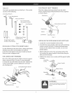
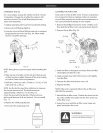

ROCKER ARM CLEARANCE ADJUSTMENT
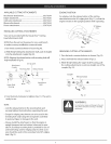
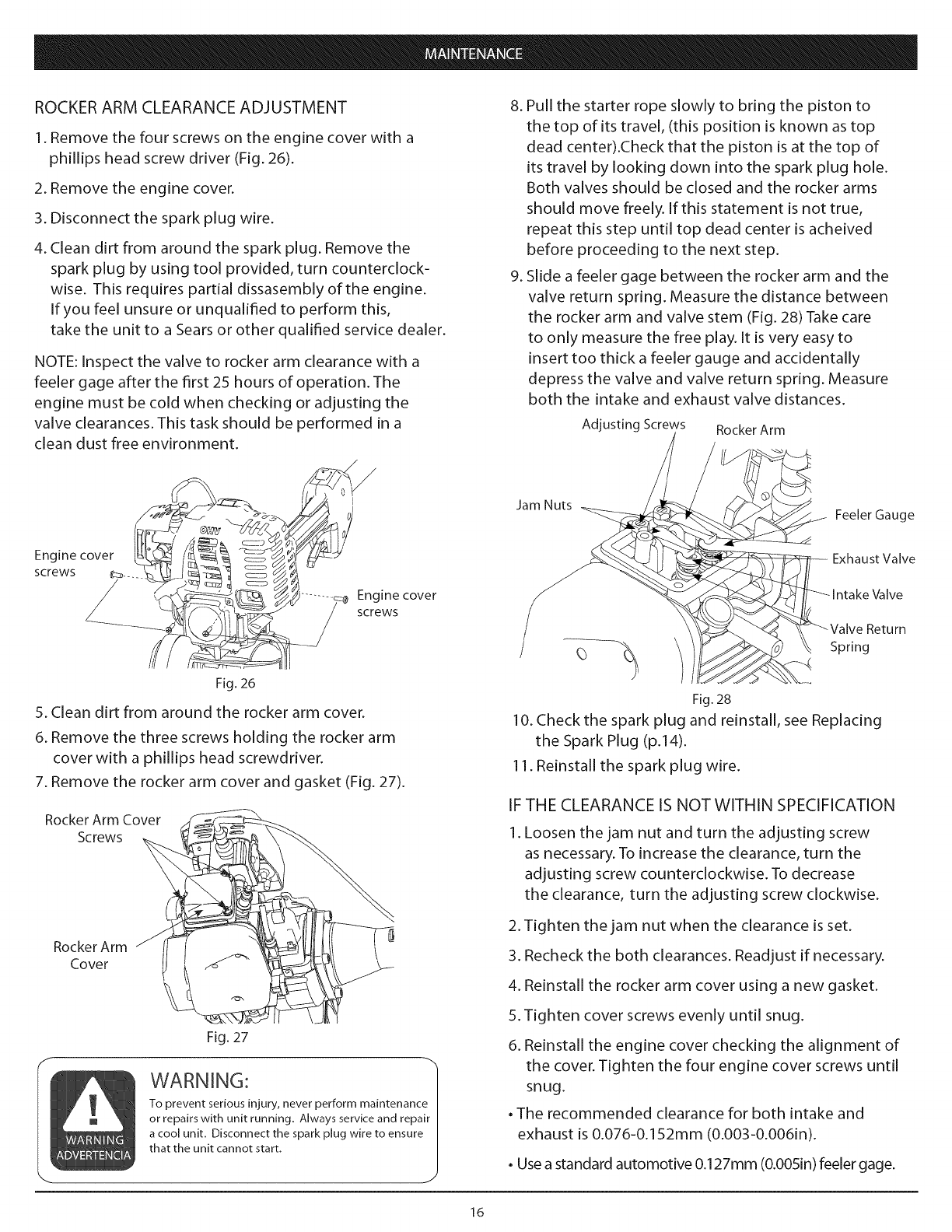
1.Remove the four screws on the engine cover with a
phillips head screw driver (Fig. 26).
2. Remove the engine cover.
3. Disconnect the spark plug wire.
4. Clean dirt from around the spark plug. Remove the
spark plug by using tool provided, turn counterclock-
wise. This requires partial dissasembly of the engine.
If you feel unsure or unqualified to perform this,
take the unit to a Sears or other qualified service dealer.
NOTE: Inspect the valve to rocker arm clearance with a
feeler gage after the first 25 hours of operation. The
engine must be cold when checking or adjusting the
valve clearances. This task should be performed in a
clean dust free environment.
8. Pull the starter rope slowly to bring the piston to
the top of its travel, (this position is known as top
dead center).Check that the piston is at the top of
its travel by looking down into the spark plug hole.
Both valves should be closed and the rocker arms
should move freely. If this statement is not true,
repeat this step until top dead center is acheived
before proceeding to the next step.
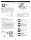
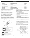
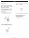
9. Slide a feeler gage between the rocker arm and the
valve return spring. Measure the distance between
the rocker arm and valve stem (Fig. 28) Take care
to only measure the free play. It isvery easy to
insert too thick a feeler gauge and accidentally
depress the valve and valve return spring. Measure
both the intake and exhaust valve distances.
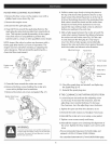
Adjusting Screws Rocker Arm
Jam Nuts
Feeler Gauge
Engine cover
screws _ ....
Z
Engine cover
screws
Fig. 26
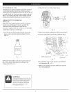
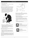
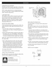
5. Clean dirt from around the rocker arm cover.
6. Remove the three screws holding the rocker arm
cover with a phillips head screwdriver.
7. Remove the rocker arm cover and gasket (Fig. 27).
Rocker Arm Cover
Screws
RockerArm
Cover
Fig. 27
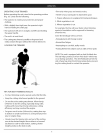
WARNING:
To prevent serious injury, never perform maintenance
or repairs with unit running. Always service and repair
a cool unit. Disconnect the spark plug wire to ensure
that the unit cannot start.
Exhaust Valve
_'_ Intake Valve
Return
Spring
Fig.28
10. Check the spark plug and reinstall, see Replacing
the Spark Plug (p.14).
11. Reinstall the spark plug wire.
IF THE CLEARANCE IS NOT WITHIN SPECIFICATION
1. Loosen the jam nut and turn the adjusting screw
as necessary. To increase the clearance, turn the
adjusting screw counterclockwise. To decrease
the clearance, turn the adjusting screw clockwise.
2. Tighten the jam nut when the clearance is set.
3. Recheck the both clearances. Readjust if necessary.
4. Reinstall the rocker arm cover using a new gasket.
5. Tighten cover screws evenly until snug.
6. Reinstall the engine cover checking the alignment of
the cover. Tighten the four engine cover screws until
snug.
• The recommended clearance for both intake and
exhaust is 0.076-0.152mm (0.003-0.0061n).
• Usea standard automotive 0.127mm (O.O05in)feeler gage.
16