


Page 14 Page 15
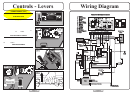
Collector AdjustmentsPowered Collector
CONNECTION
To connect the Powered Collector to the
Tractor, ensure that both are on an even
surface with the Locking Levers (fig 3)
on the collector facing the Lift Arms on
the Tractor. Move the collector manually
to the Tractor. Lower the Lift Arms using
the button (Page 6 fig 3) on the dash
console.
At the end of each Lift Arm you will find
a Locating Lug . Slide the Channels on
either side of the Powered Collector over
the Lugs but do not engage the Locating
Lever yet. Ensure that the Rubber Flap at
the opening of the PGC locates on top of
the Transmission Grass Deflector.
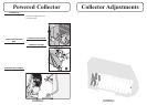
INSTALLING THE DRIVE
BELT
Place the Drive Belt over the PTO pulley
(beneath the Tractor seat). Standing
adjacent to the Tractor, extend the belt
with both hands parallel to the ground.
Now twist the belt to form a figure ‘8’-
the right-hand up and the left-hand down.
In this position place the other end of the
belt over the Powered Collector Pulley.
Be sure that this is installed the right way
round otherwise the brush will work in
reverse and collection will be poor!
Lock Locating Lever (fig 3) over the Lift
Arm Lugs . Rotate Locking Clips over
Lift Arm Lugs.
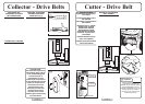
PTO DRIVE BELT TENSION
Engaging the Locating Lever tensions the
belt which should not be run too tight - to
check the tension there should be a 19mm
deflection with light finger pressure
(2Kgs) at a midway point between PTO
pulley and Sweeper pulley. It is
important after attaching the Sweeper to
the Tractor, to check the Belt Tension and
adjust this if necessary; this must be done
before the Sweeper is put into operation
and with the Sweeper on the ground.
With light finger pressure, 2kgs (4lbs),
there should be a total deflection of
19mm (3/4”) at midway point between
PTO pulley and the Sweeper pulley. If a
spring balance is available a pressure of
4-5lbs (1.81-2.26Kgs) is required for a
deflection of 3/4” (19mm).If the Belt
Tension is incorrect it can be adjusted by
movement of Sweeper Locking Levers
on the threaded rod. Ensure the lock nuts
are suitably tightened after adjustment.
N.B. Do not overtighten lock nuts as
lever needs to pivot.
TO USE: RAISE SWEEPER TO THE
TRANSPORT POSITION
Using the switch on the dashboard, lift
the PGC to the transport position. We
recommend that you drive to and from
the area to be swept with the Powered
Collector in this transport position and
with the P.T.O disengaged.
When you reach the area to be swept,
lower the collector and then engage the
brushes by pushing the sprung PTO lever
to the right to release and engage.
LOWER THE COLLECTOR
Using the lever (page 15 fig 2), lower the
collector.
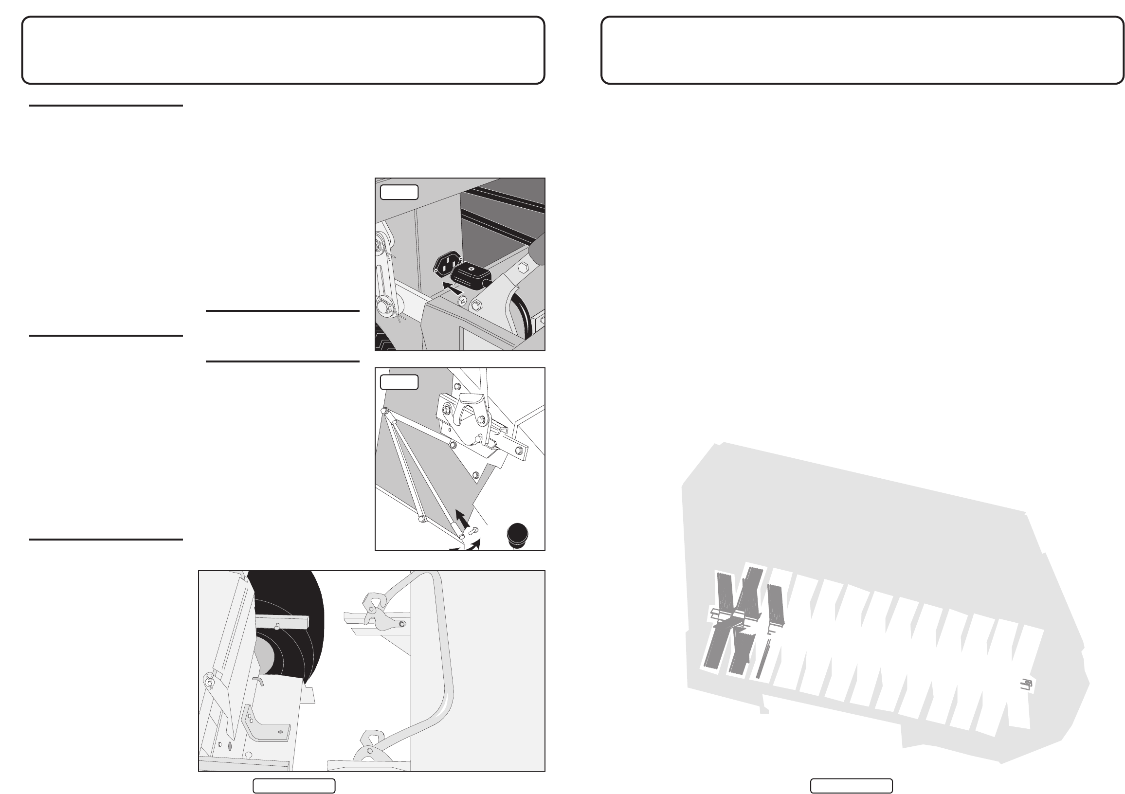
REMOVING THE NET
When removing the net, we suggest you
employ the assistance of another person.
1. Partially open the Sweeper net
(100mm (4”)). Disconnect opening rod
by pulling back on sprung locking tube
and uncoupling from pin (fig 2).
2. Repeat either side.
3. Undo net locking clip (both sides),
unhook levers from locating pins
(see fig 2).
4. With either person standing each side
of the collector net, slide the net off the
locating arms.
5. Reverse operation for fitting.
fig 1
fig 2