


4
Catalyst 6500 Series Supervisor Engine Flash PC Card Installation Note
78-6507-06
Installing and Removing a Flash PC Card
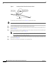
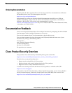
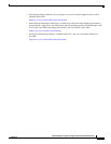
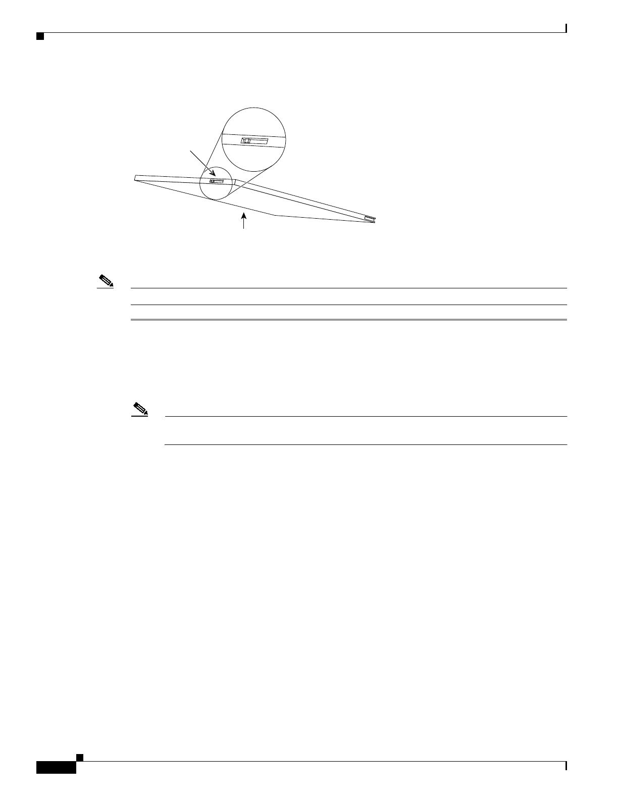
Figure 2 Locating the Flash PC Card Write Protection Switch
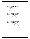
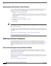
To install and remove a Flash PC card (see Figure 3), perform these steps:
Note You can insert and remove the Flash PC card with the power on.
Step 1 Connect an ESD-preventive strap to the ESD connector on the switch.
Step 2 Face the front panel of the switch, and hold the Flash PC card with the connector end toward the slot, as
shown in Figure 3a.
Step 3 Insert the card into the slot until it completely seats in the connector at the back of the slot and the eject
button pops out toward you, as shown in Figure 3b.
Note The card does not insert all the way inside the slot; a portion of the card remains outside the slot.
Do not attempt to force the card past this point.
Step 4 To eject a Flash PC card, press the ejector button until the card is free of the connector at the back of the
slot, as shown in Figure 3c.
Step 5 Remove the card from the slot and place it in an antistatic bag.
Flash PC card
Flash PC card
write protection
Flash PC card
shown with write
protection off
H2352