


Page 6SKU 02810 For technical questions, please call 1-800-444-3353.
any doubt about the safety issues involved, have a qualified, certified, arborist/tree
surgeon do the work for you.
21. WARNING: Some dust created by power sanding, sawing, grinding, drilling, and
other construction activities, contain chemicals known (to the State of California) to
cause cancer, birth defects or other reproductive harm. Some examples of these
chemicals are: lead from lead-based paints, crystalline silica from bricks and ce-
ment or other masonry products, arsenic and chromium from chemically treated
lumber. Your risk from these exposures varies, depending on how often you do this
type of work. To reduce your exposure to these chemicals: work in a well ventilated
area, and work with approved safety equipment, such as those dust masks that are
specially designed to filter out microscopic particles. (California Health & Safety
Code § 25249.5,
et seq.
)
22. WARNING: We recommend that people with pacemakers not use this tool. This
tool produces strong electromagnetic fields that can cause interference or failure of
the pacemaker. People with pacemakers should consult their physician(s) for ad-
vice.
ASSEMBLY INSTRUCTIONS
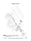
NOTE: For additional references to the parts listed in the following pages, refer to the
Assembly Diagram on page 12.
To Attach Or Replace The Chain Guide Rail And Chain:
1. WARNING: Make sure to turn the On/Off Trigger (25b) to its “OFF” position and un-
plug the Electric Cord (23) from its electrical outlet before performing this procedure.
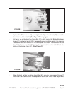
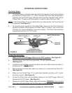
2. Remove Screw (7) and Nylon Insert Nut (67) from the Chain Cover (46) with the
tools provided. Note the Blade Guide Pin (62) and Bolt (6) shown in Figure B. Make
sure the Guide Pin is positioned near the rear (left end) of the slot. Make certain that
the oil port is open and free of debris.
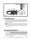
3. Place the Chain (57) around the rear of the Chain Gear (45), making certain that the
teeth along the top of the Chain point forward.
4. Place Guide Bar (52) with the center slot over the threaded end of the Bolt (66), and
fixed pin (molded into the Front Cover (42)), as in Figure C. The Blade Guide Pin
(62) goes into the lower hole in the blade. These steps may be easier with assis-
tance.
UNPACKING
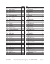
When unpacking, check to make sure all the parts shown on the Parts List on page 11
are included. If any parts are missing or broken, please call Harbor Freight Tools at the
number shown on the cover of this manual as soon as possible.
REV 05/05