


Page 24 of 26 Intimidator™ Spot LED 350 User Manual (Rev. 02)
(DMX Connectivity cont.)
Number of Fixtures
When using a DMX controller, the combined number of channels required by
all the fixtures on the DMX daisy chain determines the number of fixtures the
DMX controller has to support. Conversely, the number of onboard sliders,
page buttons, and fixture buttons limits the number of discrete DMX channels
a DMX controller can support.
To comply with the EIA-485 standard, which is the base for the USITT
DMX512-A protocol, do not connect more than 32 fixtures without using
an optically-isolated DMX splitter. Doing otherwise may result in
deterioration of the digital DMX signal.
DMX Data Cabling
You must use DMX compliant data cables to link two or more DMX compatible
fixtures. You may purchase CHAUVET® certified DMX cables directly from a
dealer/distributor or construct your own cable.
USITT recommends limiting the total length of the DMX cable (from the
first fixture/controller to the last fixture) to 300~455 m (985~1,500 ft).
Making Your Own
DMX Cable
If you choose to create your own DMX cable, make sure to use data-grade
cables that can carry a high frequency signal and are less prone to
electromagnetic interference. Use a Belden® 9841 or equivalent cable, which
meets the specifications for EIA RS-485 applications. For certain applications,
Cat5, Cat5e, or Cat6 may be appropriate.
Do not use standard microphone cables for DMX applications because
they cannot transmit DMX data reliably over long distances.
DMX Cable Characteristics
The DMX data cable must have the following characteristics:
Type: shielded, 2-conductor twisted pair
Maximum capacitance between conductors: 30 pF/ft
Maximum capacitance between conductor and shield: 55 pF/ft
Maximum resistance: 20 ohms/1000 ft
Nominal impedance: 100~140 ohms
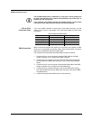
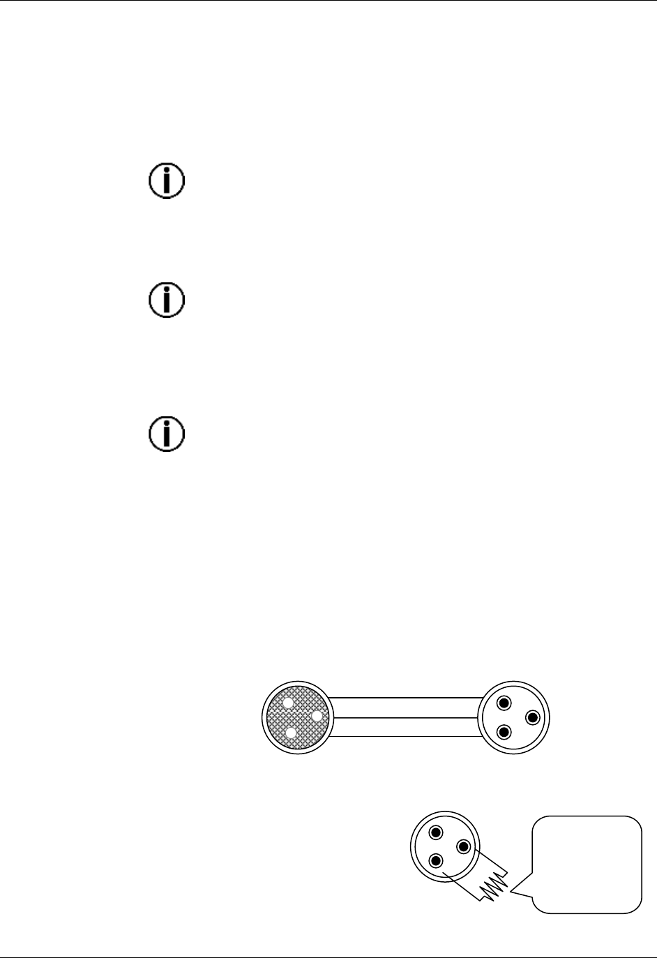
DMX Cable Connectors
Each DMX cable must have a male (3-pin or 5-pin XLR connector) on one end
and a female (3-pin or 5-pin XLR connector) on the other end.
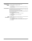
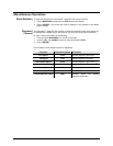
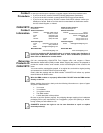
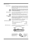
To avoid signal transmission
problems and interference,
connect a DMX signal terminator
to the last fixture in the
DMX daisy chain, as shown.
To DMX Input
(Female)
DMX Connector Configuration
Common
DMX +
DMX -
1
3
2
1
3
2
To DMX Output
(Male)
120 ohm, ¼ W
resistor between
pin 2 (DMX -) and
pin 3 (DMX +) on
the output of the
last fixture.
1
3
2