


Intimidator™ Spot LED 350 User Manual (Rev. 02) Page 25 of 26
(DMX Connectivity cont.)
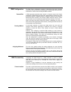
Test all DMX cables with an ohmmeter to verify their correct polarity and
to make sure that there are no short-circuits between any of the pins, or
between any pin and ground.
If the common wire (shield) touches the chassis ground, a ground loop
could form, which may cause the fixture to perform erratically.
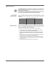
3-Pin to 5-Pin
Conversion Chart
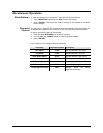
If you use a DMX controller or fixture with a 5-pin DMX connector, you will
need to use a 5-pin to 3-pin adapter. The chart below details a proper cable
conversion.
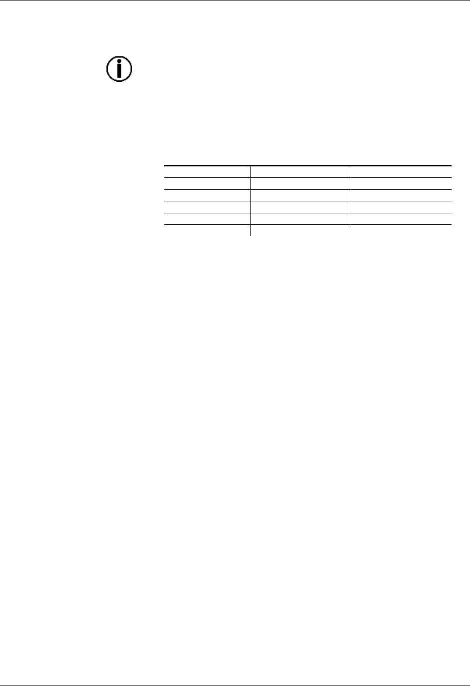
3-Pin to 5-Pin Conversion Chart
Conductor
3-Pin Female (Output)
5-Pin Male (Input)
Ground/Shield
Pin 1
Pin 1
Negative (-) signal
Pin 2
Pin 2
Positive (+) signal
Pin 3
Pin 3
Not Used
Pin 4
Not Used
Pin 5
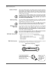
DMX Connection
Make sure that the fixtures with which you are working can operate in DMX
mode, not in a proprietary connection mode. Refer to the fixtures’ manual to
learn how to enable their respective DMX modes.
The procedure below illustrates a possible DMX connection method.
1. Connect the 3-pin, male connector of the first DMX cable to the DMX
Output connector (3-pin, female) of the DMX controller.
2. Connect the 3-pin, female connector of the first DMX cable coming from
the controller to the DMX Input connector (3-pin, male) of the first DMX
fixture.
3. Connect the 3-pin, male connector of the second DMX cable to the DMX
Output connector (3-pin, female) of the first DMX fixture.
4. Connect the 3-pin, female connector of the second DMX cable coming
from the first DMX fixture to the DMX Input connector of the second DMX
compatible fixture.
5. Continue linking the other DMX fixtures in the same way.