


17
®
3
DUAL W85 INSTALLATION
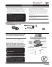
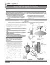
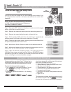
To control the fan and lights from two locations (a three-way circuit), use two W-85
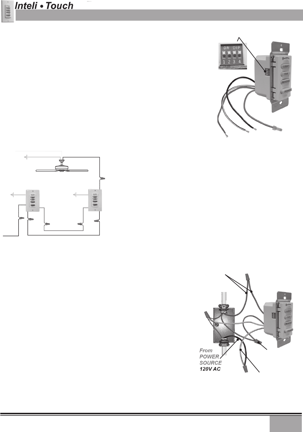
wall controls as shown in the wiring diagram in Figure #5. Before installing the
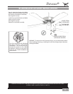
two switches into the wall, place both switches side by side, then locate the 4 dip
switches on the side of the two switches. Then make sure that the dip switches
are set to the same address on both switches as shown in Figure #4. When setting
these dip switches you are setting the channel number that is required to control
both your fan and lights from both sides of the room. If you are installing other
Inteli-Touch
®
3 fans within your home you may need to reset the dip switches on
these other fans to a different channel before installing your W-85 wall control into
the wall. Please review the section on channel changing on this instruction sheet.
(FIGURE #4)
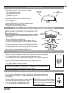
Ensure power is turned OFF at the breaker or fuse panel before
starting installation.
To control the fan and lights from two locations (a three-way circuit), use two
W-85 wall controls.
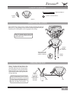
1. Remove the screws and switch plate from the existing switch box
and the screws holding the switch in the switch box.
2. Pull the existing switch from the switch box to expose the wire con-
nections.
3. Determine which wire is connected to the common terminal from
the power source (120V AC) of the three-way switch. (The terminal
will be marked on switch).
4. Remove the wire from the common terminal of the three-way switch.
Connect this wire to the remaining black/white striped wire on the W-85
control. Secure this splice with a wire nut.
5. Remove the two remaining wires from the three-way switch. Con-
nect the black wire of these wires to a black wire on the W-85 control.
Secure the splice with a wire nut. The remaining red wire is to be con-
nected to the other red wire on the
W-85. Secure the splice with a wire nut.
6. Connect the green ground wire coming from the back of the W-85 con-
trol to the ground wire in the switch box. Secure the splice with a wire
nut.
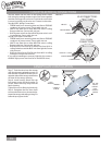
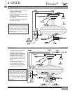
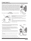
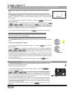
7. Check your work by using the wiring diagrams as shown in Figure #5
on this page.
8. Install the W-85 in the wall box with the two long screws provided.
9.Install the wall plate with the two short color-matched screws provided.
10.Installation of the second W-85 control is identical. Repeat steps 1 through 9.
W-85
Wall Control
STRIPED WIRE
2 RED WIRES
2 BLACK
WIRES
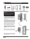
(FIGURE #5)
W-84
BLACK
BLACK
BLACK
BLACK
BLACK
BLACK
BLACK
RED
GREEN
120V AC
BLACK
BLACK WITH
WHITE STRIPE
W-84
RED
RED
RED
BLACK WITH
WHITE STRIPE
GREEN
NEUTRAL
WHITE
GREEN
W-85
W-85