


12
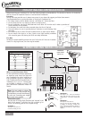
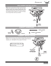
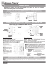
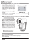
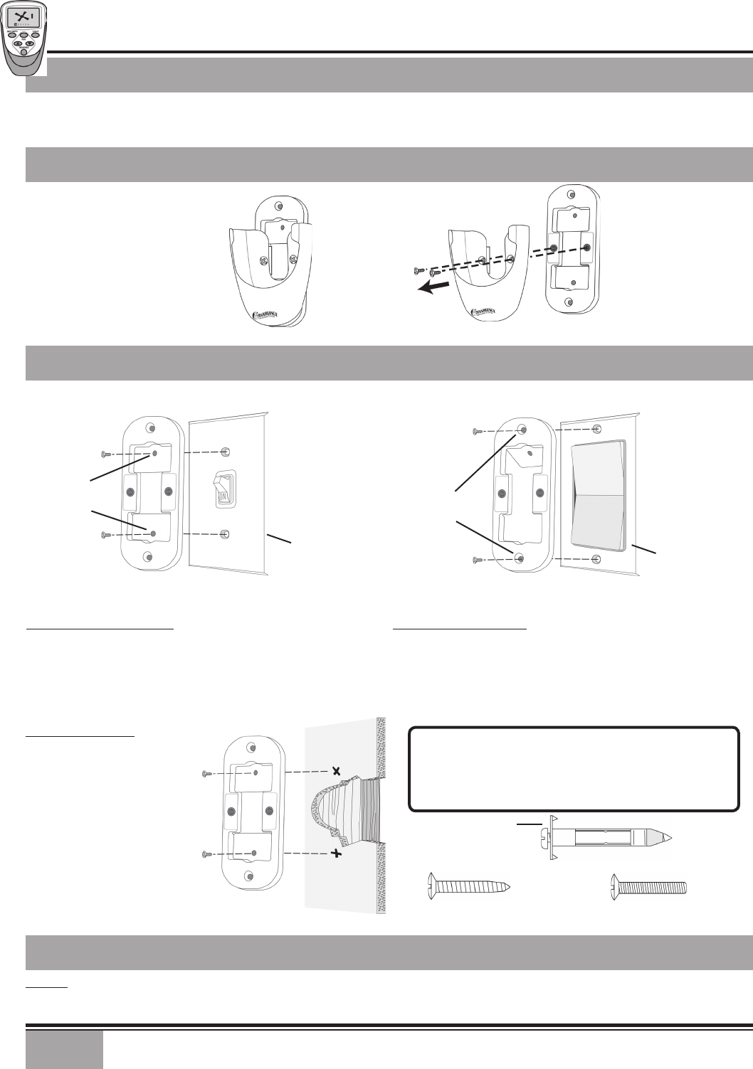
Step 1. Remove the
two 6-32 x 5/16” screws
holding the bracket to
the holster. Save screws
for later.
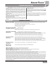
Standard Light Switch
Step A. Remove the two screws holding the switch cover
plate. Do not remove the cover plate.
Step B. Orient the control bracket as shown and line up the
two inner mounting holes with those on the switch.
Step C. Install and tighten screws by hand only.
INNER
MOUNTING
HOLES
CONTROL
BRACKET
STANDARD
TOGGLE
SWITCH
SWITCH
COVER
PLATE
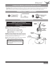
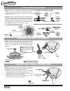
Rocker Light Switch
Step A. Break off the two tabs by pushing outward.
Step B. Remove the two screws holding the switch cover
plate. Do not remove the cover plate.
Step C. Orient the control bracket as shown and line up the
two inner mounting holes with those on the switch.
Step D. Install and tighten screws by hand only.
OUTER
MOUNTING
HOLES
CONTROL
BRACKET
ROCKER
TYPE
LIGHT
SWITCH
SWITCH
COVER
PLATE
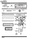
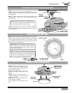
Wall Installation
Step A. Locate a 2x4
wall stud in a convenient
location.
Step B. Orient the control
bracket as shown over the
2x4 stud.
Step C. Use the 1” wood
screws in either the inner
or outer mounting holes.
Install and tighten screws
by hand only.
DECOR OVALHEAD SCREW
6-32 X 1”
ANCHOR
PANHEAD
SCREW
WOOD
SCREW 1”
DRYWALL ANCHOR
Note: The wall anchors and 6-32 x 1” screws may be
used in situations where mounting to a stud is not pos-
sible. Use the inner mounting holes. After securing the
anchor, discard the anchor’s pointed screws and use the
6-32 decor ovalhead screws supplied.
Step 2
After you have completed installing the bracket to the wall, using the 2 screws removed in Step 1, attach the W-62 holster
to the bracket.
CAUTION! Do not use with wall dimmer.
HOLSTER
BRACKET
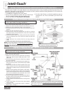
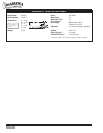
Warning: To reduce the risk of electrical shock, this fan must be installed
with an isolating wall control/switch.
SAFETY FIRST
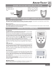
ADVAN•TOUCH
®