


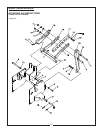

Model CBH60 Backhoe
ATTACHING KIT INSTRUCTIONS
3-POINT HITCH LINKAGE & HYDRAULIC HOOK-
UP TO TRACTOR HYDRAULIC SYSTEMS
General Description
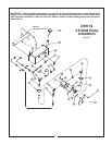
Mounting and hydraulics kits do not include hoses
which connect the backhoe control valve to the trac-
tor hydraulic system. Additional hydraulic compo-
nents, hoses, and / or kits will be required to complete
hook-up to the tractor hydraulic system. Refer to the
Hydraulic Hook-up section for further information.
The backhoe is mounted on the tractor lower link
arms and an adjustable upper link is supplied to
replace the tractor upper link. A set of stabilizer arms
is included. They bolt from the adjustable upper link
to the backhoe mainframe, locking the hoe rigidly in
one position.
IMPORTANT: Tractor lower links must be kept
free of lifting forces at all times after installation
of the attaching kit, by keeping tractor quadrant
lever in the lowered position.
ASSEMBLY
IMPORTANT: Tighten all hardware to the torque
requirements specified in the torque chart.
!!
WARNING!
To prevent bodily injury, do not operate backhoe
unless Lower Link Weldments (28, 29) are proper-
ly installed and adjusted. Failure to do so may
result in backhoe being thrust upward, crushing
operator against cab or ROPS.
1. Use hoist to raise the backhoe mainframe so that
the boom pivot pin is approximately 12” off the
ground.
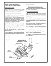
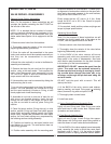
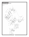
2. Attach Right Hand and Left Hand Lower Link
Mount Weldments (21, 22) and Seat Upper Link
Weldment (23) to backhoe Mainframe Weldment
using eight 5/8NF x 2” Bolts (3), Hardened
Washers (15) and Nuts (10). Do not tighten hard-
ware at this time.
3. Install Right and Left Hand Floor Pans (24, 25) to
Seat Upper link Weldment (23) using four 3/8NC
x 1” Carriage Bolts (1), Lockwashers (12), and Nuts (8).
4. Install Seat Assembly from base backhoe to
Seat Upper Weldment (23) using hardware pro-
vided with base backhoe, consisting of four
1/2NC x 1-3/4” Carriage Bolts, Lockwashers, and Nuts.
5. Tighten and torque all hardware installed.
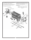
6. Back tractor close to the backhoe. Connect tractor
lower link arms to lower link mounts using two L-pins
(20), two Cotter Pins (17), and two Wire Form Cotter
Pins (18).
NOTE: If tractor has a Category II hitch, install two
Bushings (30) in lower link arms.
7. Attach Upper Braces (27) to backhoe with 3/4NF x
7-1/2 Bolt (6), Lockwasher (14), Washers (16) and Nut
(11). Do not tighten hardware at this time.
8. Install Bushing (19) or Bushing (31) in the hole of the
Upper Bar (26) that most closely matches the diameter
of the tractor upper link pin. No bushing is necessary
for Category II tractors.
9. Secure Upper Bar (26) between Upper Braces (27)
using 3/4NF x 4” Bolt (5), Washers (16), Lockwasher
(14) and Nut (110. Use hoist to raise or lower back-
hoe slightly until a hole in the Upper Bar aligns with a
hole in the Upper Braces.
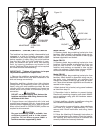
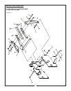
10. Attach RH Lower Link Weldment (28) and LH Lower
Link Weldment (29) to backhoe mainframe using
3/4NF x 2-1/4” Bolt (4), Washers (16), Lockwasher
(14), and Nut (11).
11. Align RH and LH Link Weldment (28, 29) with a hole in
the Upper Bar/Brace assembly, as close to the tractor
as possible. Use 3/4NF x 5-1/2” Bolt (7), Washers (16),
Lockwasher (14), and Nut (11). You may need to
return to step 6 and readjust upward or downward the
bolt connection. You may also need to switch the Right
and Left Hand Link weldments on the backhoe to
obtain proper clearances with tractor components.
12. Remove backhoe from the tractor.
13. Install Connector Plate (32) to RH and LH Lower Link
Weldments (28, 29) using 1/2NF x 1-3/4” bolt (2),
Lockwasher (13), and Nut (9).
14. Tighten all hardware at this time.Check your installation
very carefully to be sure all members are correctly
installed and securely fastened.
15. Connect hoses from the backhoe control valve to the
tractor hydraulic system as described in “Hydraulic
Hook-Up” section, prior to remounting the backhoe
onto the tractor.
30