


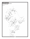

MODEL CBH 70, CBH 80
VALVE REPAIR - DISASSEMBLY
Replace Center Section Assemblies:
Note: For the purpose of these instructions we will
consider the section containing the INLET PORT as
the left side of the valve.
NOTE: If it is decided that an overhaul of compo-
nents or pressure adjustments are necessary to cor-
rect malfunctioning, it is recommended that your
dealer make these repairs. He is equipped to do this
work.
1. Remove control valve from the backhoe.
2. Thoroughly clean the exterior of the valve before
beginning disassembly procedures.
3. Since the valve will be assembled in the same
order, each section should be marked numerically so
that they can be reassembled in the same
sequence.
4. Mount the valve vertically in a vise to facilitate dis-
assembly and assembly.
5. Remove the three tie rod nuts from the right end
section, using a thin-wall socket. Tools required for
basic valve disassembly and reassembly include
1/2” and 9/16” open or box end wrenches and a
torque wrench with thin wall sockets.
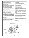
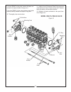
6. Valve sections can now be removed by sliding the
sections along the tie rods.
7. Lay out valve components on a clean, flat working
surface. The inlet assembly will include an O-ring,
and the spool section(s) include an O-ring, a load
check poppet and a load check spring.
8. Assemble tie rod nuts to one end of each tie rod
with one or two threads showing. Insert tie rods
through tie rod holes of inlet (larger tie rod at top).
Lay inlet on end with tie rods up, place O-ring into
position.
9. Place first spool section (O-ring side up) on inlet
section, position O-ring and insert load check poppet
(nose down) and spring (behind poppet) into loader
check cavity. Repeat this procedure for each spool
section; the load check springs are compressed by
the following sections during assembly.
10. Position end section on last spool section and
hand tighten tie rod nuts. The end section does not
have O-ring grooves.
11. Position valve assembly with the mounting pads
of the end sections on a flat surface. To obtain prop-
er alignment of end sections relative to the spool sec-
tions apply downward pressure to the end sections;
snug tie rod nuts to about 10 ft. lbs.
Finally torque the two 1/2” nuts to 14 ft. lbs.; finally
torque the 9/16” nut to 33 ft. lbs. Check for proper
spool movement.
12. As required, install auxiliary valves and plugs and
torque to proper specifications.
Replacing Spools Seals:
Note: For the purpose of these instructions we will
consider the control handle side of the valve as the
FRONT, and the opposite side as the BACK.
1. Remove control valve from the backhoe.
2. Thoroughly clean the exterior of the valve before
beginning disassembly procedures.
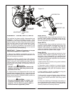
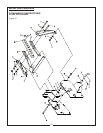
3. At the BACK of the valve remove all bonnet
assembly parts whick are connected to the spool.
Keep parts in the order of disassembly. See each
valve section parts breakdown for the parts involved
in the make-up of the bonnet assembly.
IMPORTANT: DO NOT remove the spool from the
valve. The seals can be replaced externally.
Prevent spools from turning or moving by insert-
ing a screw driver through the clevis slot, or by
running a rod through the pin hole and using the
rod as a handle.
DO NOT hold the spool with a wrench. This will
destroy the finish.
4. At the BACK of the valve, remove seal retainer,
back-up washer, and spool O-ring seal, or retaining
sleeve, bonnet O-ring seal and spool O-ring.
5. Thoroughly clean counter bores.
6. Install new seals:
A. Spring-Centered Bonnet Assembly Only:
Lightly oil new O-ring seal. Slide O-ring over valve
spool and insert in seal counter bore. Replace back-
up washer and seal retainer.
B. Float Bonnet Assembly Only:
Lightly oil new O-rings. Install O-rings into spacer.
Slide spacer with O-rings over spool being careful to
orient as shown in boom valve section breakdown.
7. At the BACK of the valve replace bonnet assembly
parts, reversing the order in which they were disas-
sembled in step 3. Use 6 - 8 ft. lbs torque to tighten
assembly screw on spring centered bonnet assem-
26