


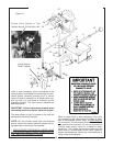
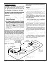
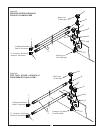

Skid Steers with an auxiliary hydraulic flow of 15
gpm or less - Figure 29
Assemble straight male adapter (6) to “K3” port on
valve as shown in Figure 29. Assemble JIC swivel
run tee (9) to straight male adapter (6). Assemble
90° male adapter (10) to “K2” port on valve.
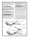
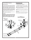
Skid Steers with an auxiliary hydraulic flow
greater than 15 gpm - Figure 30
Assemble straight male adapter (6) to “K2” port on
valve as shown in Figure 30. Assemble JIC swivel
run tee (9) to straight adapter (6). Assemble 90°
male adapter (10) to “K3” port on valve.
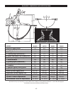
IMPORTANT - The location of the JIC swivel run
tee will ensure that proper flow is provided to the
backhoe for smooth operation. The flow into the
valve from the skid steer is divided between the
two outlet ports “K2” and “K3”. The hydraulic
flow is split so that 60% is flowing from the “K2”
port and 40% is flowing from the “K3” port.
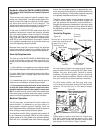
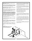
4. Assemble 90° JIC adapter (8) to through port of
swivel run tee fitting (9).
5. Assemble 45° JIC adapters (7) to both
“In/Pressure” and “Out/Return” ports on the backhoe
bulkhead connection.
6. Connect 24” hydraulic hose (11) between 45° JIC
adapter (7) on backhoe “In/Pressure” bulkhead con-
nection and single 90° male adapter (10) located on
top of flow divider valve.
7. Connect 24” hydraulic hose (11) between 45° JIC
adapter (7) on backhoe “Out/Return” bulkhead con-
nection and JIC swivel run tee (9) on flow divider
valve.
8. Assemble quick coupler (supplied by customer) to
pressure line hydraulic hose (supplied by customer)
and connect free end of hose to 90° male adapter
(10) at bottom of flow divider valve.
9. Assemble quick coupler (supplied by customer) to
return line hydraulic hose (supplied by customer)
and connect free end of hose to 90° JIC adapter (8)
on flow divider valve.
10. Carefully route pressure and return line hydraulic
hoses to tractor hydraulic connections. Remove dust
caps from tractor hydraulic connections and connect
hoses to the appropriate port on tractor.
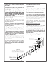
Testing Backhoe Hydraulic Hook-Up
1. Start skid steer loader engine.
2. Set parking brake and engage auxiliary boom
hydraulics so that oil flows to backhoe. NOTE!
Consult skid steer Operator’s Manual for proper
operation.
3. Exit skid steer and sit in backhoe operator’s seat.
4. To remove air from backhoe hydraulic system,
slowly cycle all backhoe functions (stabilizers, boom,
dipperstick, bucket, and swing) several times. Be
sure to cycle stabilizers first and then lower both sta-
bilizer arms into operating position before cycling
other backhoe functions.
5. Exit backhoe, disengage auxiliary boom
hydraulics, stop engine, and check skid steer
hydraulic fluid level.
40
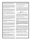
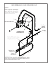
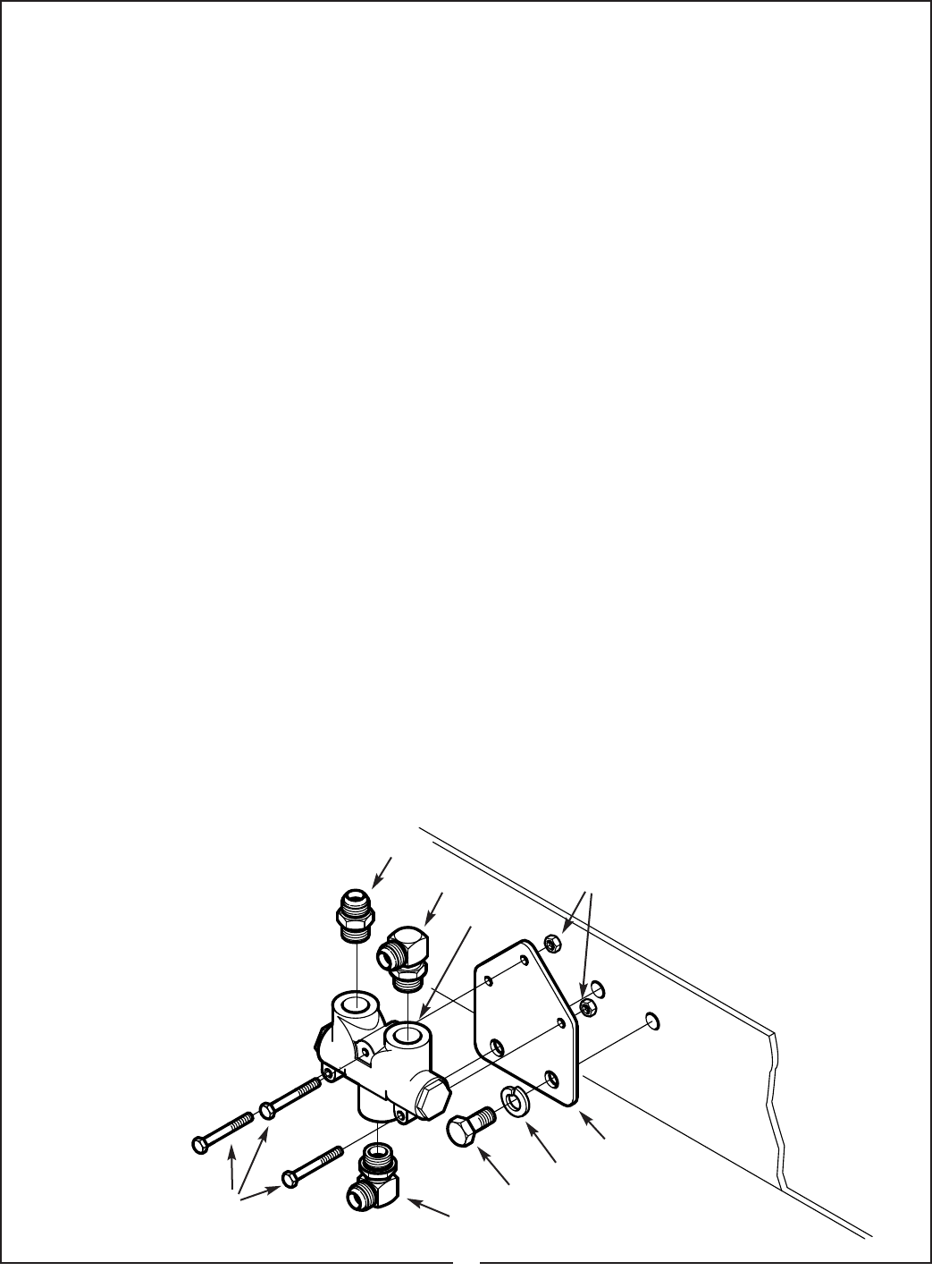
Figure 28
FLOW DIVIDER VALVE TO SKID
STEER ADAPTER MOUNTING
6
10
5
3
12
4
2
10
1