


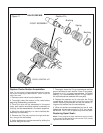
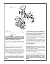
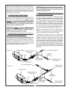
ASSEMBLY
IMPORTANT: Tighten all hardware to the torque
requirements specified in the torque chart on page 45.
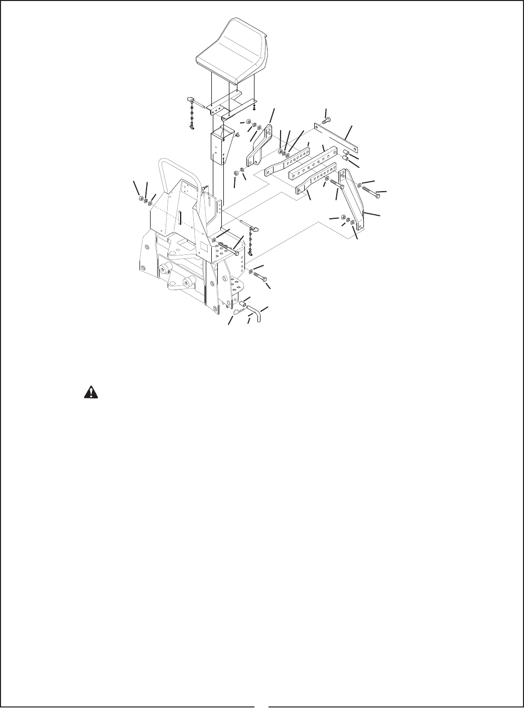
To prevent bodily injury, do not operate backhoe
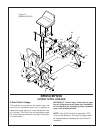
unless Link Weldments ( Figure 16 - Items 1 & 2)
are properly installed and adjusted. Failure to do
so may result in backhoe being thrust upward,
crushing operator against cab or ROPS.
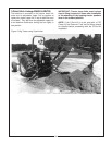
1. Use hoist to raise the backhoe mainframe so that
the boom pivot pin is approximately 17” off the
ground.
2. Back tractor close to the backhoe. Connect tractor
lower link arms to lower link mounts at position “C”,
Figure 17, using two L-pins (3), two cotter pins (4), and
two wire form cotter pins (5) as shown in Figure 16.
NOTE:
If tractor has a Category II hitch, install two
bushings (6) in lower link arms as shown in Figure 16.
3. Attach upper braces (7), Figure 16, to backhoe with
3/4 x 7-1/2” bolt (8), flat washers (9), lockwasher (10)
and nut (11). Do not tighten hardware at this time.
4. Install bushing (12) or bushing (13) that most
closely matches the diameter of the tractor upper link
pin in the hole of the upper bar (14), as shown in
Figure 16. No bushing is necessary for Category II
tractors.
5. Secure upper bar (14) between upper braces (7)
using 3/4 x 4-1/2” bolt (15), flat washers (9), lock-
washer (10) and nut (11). Use hoist to raise or lower
backhoe slightly until a hole in the upper bar aligns
with a hole in the upper braces. See Figure 16.
6. Attach RH lower link weldment (1) and LH lower
link weldment (2) to backhoe mainframe using 7/8” x
2-1/2” bolt (16), flat washers (17), lockwasher (18),
and nut (19). See Figure 16.
7. Align RH and LH link weldment (1, 2) with a hole in
the upper bar/brace assembly, as close to the tractor
as possible. Use 3/4 x 6” bolt (20), flat washers (9),
lockwasher (10), and nut (11). See Figure 16. You may
need to return to Step 6 and readjust the bolt connec-
tion upward or downward .
8. Remove backhoe from the tractor.
9. Install connector bar (21) to RH and LH lower link
weldments (1, 2) using 1/2 x 1-1/2” bolt (22), lockwash-
er (23), and nut (24). See Figure 16.
10. Tighten all hardware at this time. Check your instal-
lation very carefully to be sure all members are correct-
ly installed and securely fastened.
11. If using optional PTO Pump Kit, proceed to that
section prior to mounting the backhoe onto the tractor.
12. Connect hoses from the backhoe control valve to
the tractor hydraulic system as described in “Hydraulic
Hook-Up” section, prior to mounting the backhoe onto
the tractor.
29
Figure 16
(BH850 & BH950
11
9
10
9
8
6
16
3
23
24
11
10
9
1110 9
7
14
22
21
12
13
9
20
2
9
157
19
18
17
1
17
4
5
WARNING