


CONTROLS
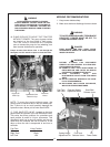
OPERATOR INTERLOCK SYSTEM
Your Bush Hog Zero Turn Riding Mower is equipped
with an Operator Interlock System that is designed to
help prevent possible serious injuries. Understanding
and maintaining this system is vital for safe operation.
To Start Engine:
1. Blades (PTO) must be disengaged.
2. Control levers in neutral (swung out).
3. Parking brake set.
The Engine Will Kill If:
1. The operator leaves the seat with:
a. The control levers out of neutral (swung in).
b. The blades are engaged.
c. The parking brake is off.
d. All of the above.
2. The park brake is on before the control levers
are swung in.
DO NOT OPERATE MOWER IF SAFETY SWITCH-
ES ARE NOT OPERATING PROPERLY.
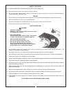
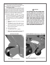
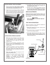
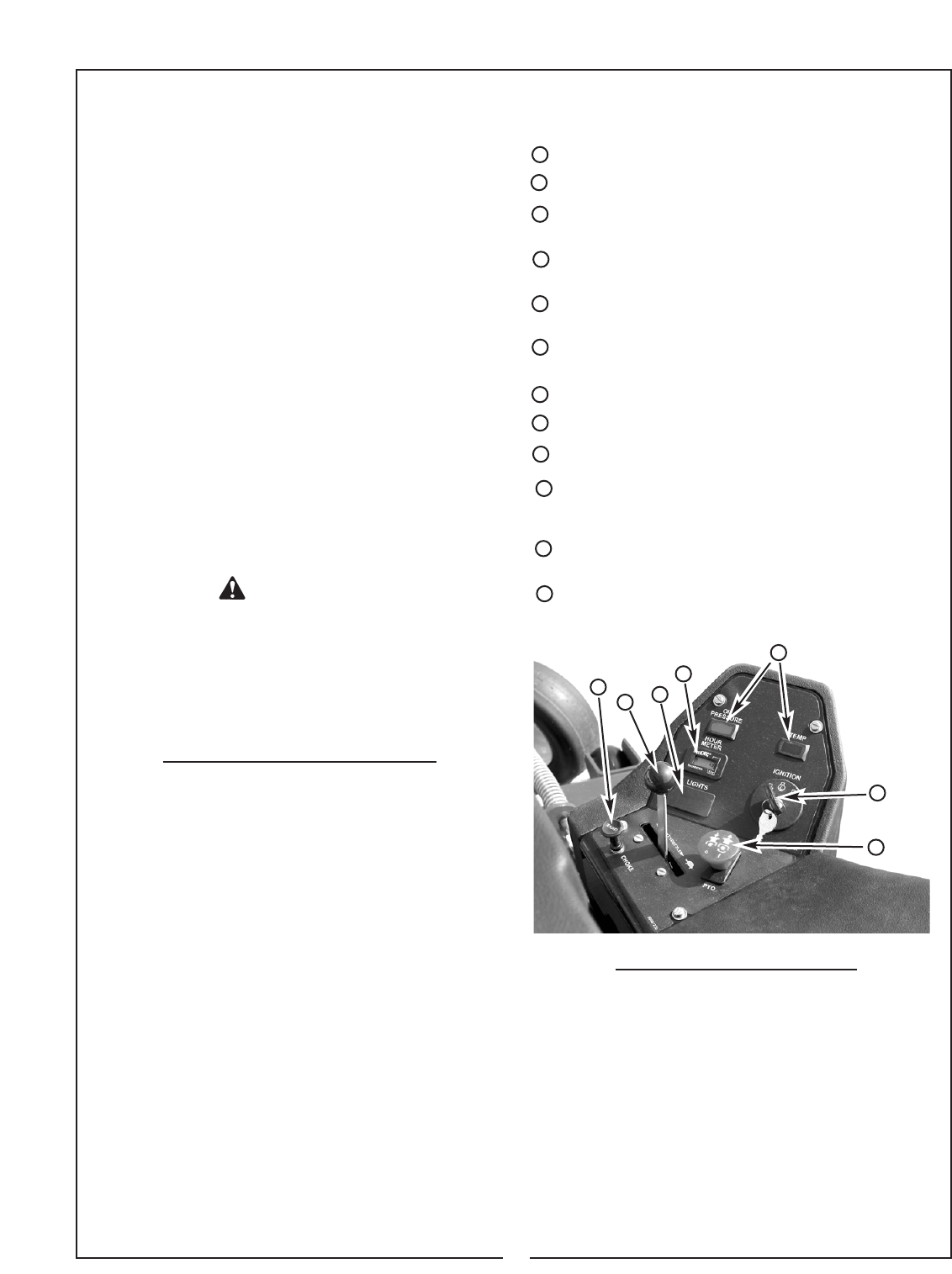
CONTROL LOCATIONS
1 Ignition Key -Starts and stops engine.
2 Engine Throttle - Controls engine speed.
3 Two Steering/Speed Control Levers - In front of
seat at side. (See page 21)
4 PTO Switch - Engages electric clutch which
engages mower blades.
5 Parking Brake Lever - Engages parking brake.
(See page 21)
6 Cutting Height Adjust Pin - Sets cutting height to
desired position. (See page 12)
7 Choke - Aids in starting engine.
8 Light Switch (Optional)
9 Hour Meter / Tachometer
10 Warning Lights / Audible Alert for high engine
temperature (Kohler models only) and oil
pressure.
11 Fuel Tank Site Lines - Monitor amount of fuel in
tank. (See page 14)
12 DC Power Outlet (See page 14)
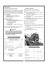
TRACTOR SPECIFICATIONS
Tread Width -49” Deck models - Outside Tires . . . . . . 50”
55” Deck models - Outside Tires . . . . . . 52”
61” Deck models - Outside Tires . . . . . . 55”
Height - To top of seat back . . . . . . . . . . . . . . . . . . . . 50”
Fuel Tank - . . . . . . . . . . . . . . . . . . . . . . . . . . 12.5 gallons
Hydrostatic Fluid Reservoir . . . . . . . . . . Approx. 1 gallon
Hydrostatic Pumps- All Models . . (2) Hydro-Gear pumps
Engines - 23 h.p. Kohler Command Pro
25 h.p. Kawasaki
21 h.p. Kawasaki
Tires - Front (49” & 55” Decks) . . . . . . . . . . . 13 x 5.0 - 6
(61” Deck) . . . . . . . . . . . . . . . . . 13 x 6.5 - 6
Drive - 49” Decks . . . . . . . . . . . . . . . 23 x 8.5 -12
55” Decks . . . . . . . . . . . . . . . 24 x 9.5 - 12
61” Decks. . . . . . . . . . . . . . . . 24 x 12 - 12
DECK SPECIFICATIONS
ITEM
Cutting width 49” 55” 61”
Cutting Height......................1-1/2” to 5” in 1/4” increments
Blades 17” 19” 21”
Overall width
including chute 61” 67” 73”
Material thickness - Deck 10 GA. 7 GA. 7 GA.
Spindle bearing......................................25 mm.................
10
WARNING
DO NOT OPERATE MACHINE UNLESS
INTERLOCK SYSTEM FUNCTIONS PROP-
ERLY. FAILURE TO HEED THIS WARNING
MAY RESULT IN SERIOUS INJURY, DEATH
OR EQUIPMENT DAMAGE.
9
8
4
7
2
1
10