


5-2 TRACTOR BALLAST
Tractor weignt bracket may be left in place on cer-
tain tractor models with loader mounted. Front trac-
tor weights can only be used when the loader is
parked. Weights must be removed before remount-
ing loader or serious damage will occur to loader or
tractor front axle due to excessive weight.
The use of adequate rear counterweight to counter-
balance for maximum loader capacity is required for
safe loader operation. Weight added to the rear of
the tractor provides better traction and easier, more
efficient loader operation.
IMPORTANT
Do not exceed the maximum load capacity of the
tires on your tractor. Refer to the Tire and Wheel
Specifications in your Tractor Operator’s Manual
for more information.
IMPORTANT
This loader has both standard and metric fasten-
ers. Verify that the proper fasteners are placed in
the correct locations. Do not tighten any bolts
firmly until all components are attached onto the
tractor.
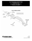
5-3 INSTALLATION
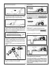
Position the tractor on a hard level surface.
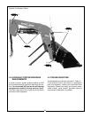
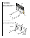
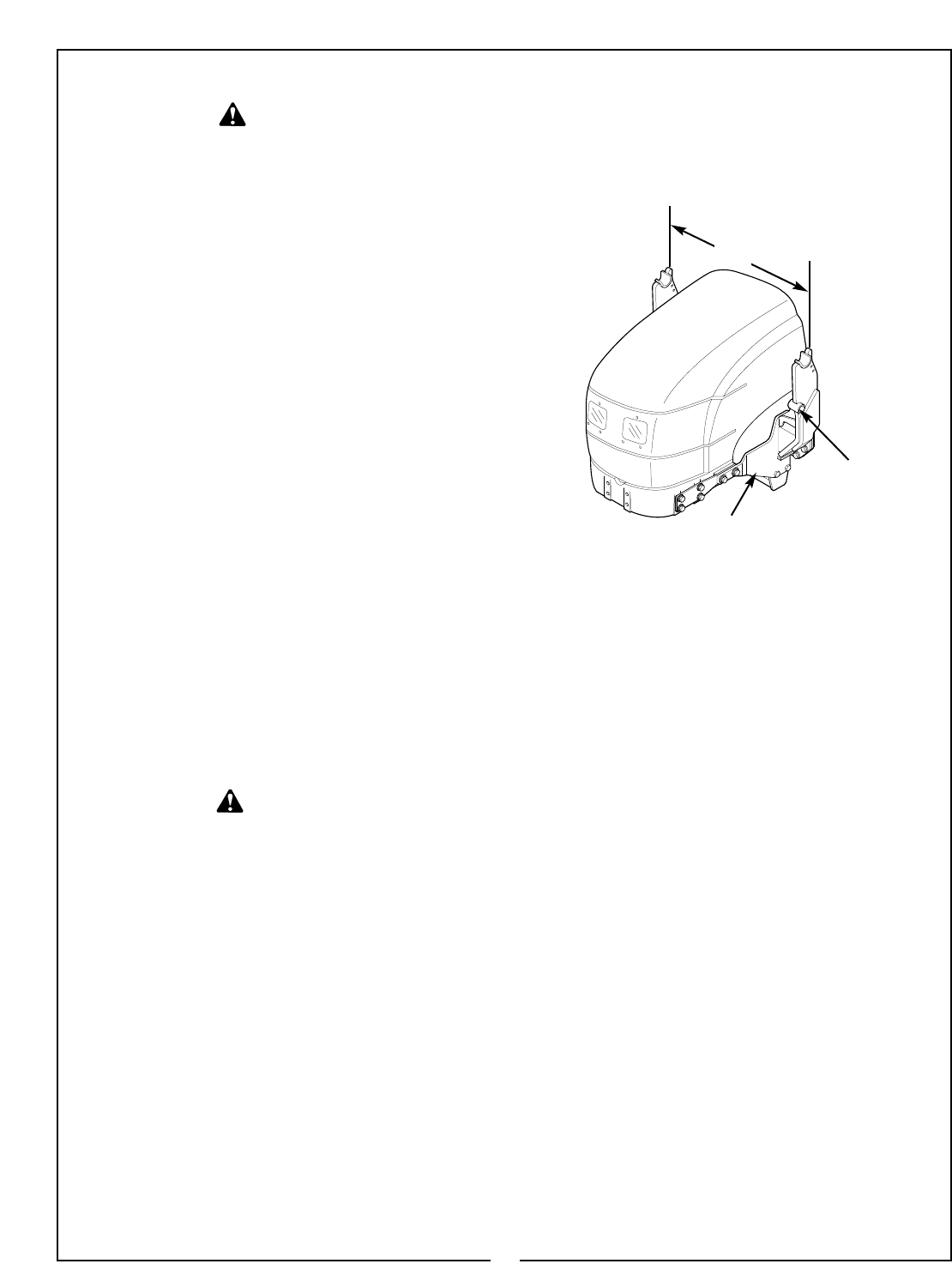
Install mounting brackets on tractor as shown in
Installation Instructions included with your Mounting
Kit. For ease of handling bracket, insert chain hook
into bracket hole. Using hoist, raise and tilt bracket
aligning mounting kit holes. Figure 5-1.
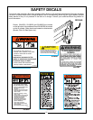
TO HELP PREVENT ROLLOVER, USE REC-
OMMENDED REAR TRACTOR BALLAST
AND WIDEST WHEEL SETTINGS TO MAXI-
MIZE STABILITY. SEE YOUR TRACTOR
OPERATOR’S MANUAL FOR RECOMMEN-
DATIONS.
CAUTION
WARNING
TO AVOID SERIOUS INJURY OR DEATH:
READ BEFORE CUTTING BANDS OR
REMOVING ATTACHING STRAPS. THE
LOADER MAY SHIFT DURING SHIPPING
AND HANDLING, MAKING IT UNSTABLE
ON THE PALLET. SUPPORT LOADER
WITH AN OVERHEAD HOIST OR OTHER
SUITABLE MEANS PRIOR TO REMOVING
BANDS OR ATTACHING STRAPS SECUR-
ING LOADER TO PALLET. FAILURE TO
DO SO COULD RESULT IN ACCIDENTAL
TIP-OVER OF THE LOADER THAT COULD
CAUSE SERIOUS INJURY TO YOU
AND/OR BYSTANDERS.
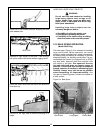
Tighten all bolts equally during installation so that
outside surface of brackets are level and the center
line measurement from right to left hand mounting
brackets (Dimension “A”) reads 32” plus or minus
1/4” for the 1045, 37” plus or minus 1/4” for the 2045
or 39” plus or minus 1/4” for the 3045. Figure 5-1.
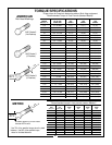
IMPORTANT
To prevent mounting kit hardware from loosen-
ing during operation, always torque mounting kit
hardware to specified torque noted in Loader
Operator’s Manual.
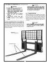
Remove all loader components from shipping pack-
aging.
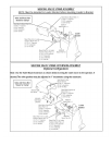
5-4 HYDRAULIC HOOKUP
For use with tractor hydraulic valve, install hoses to
loader steel tubing. Install male quick couplers (cus-
tomer furnished) to 1/2” male pipe ends of hoses.
Refer to individual instructions that come with the
various other valve and control options.
IMPORTANT
When properly installed, the tractor remote valve
or external valve control lever/levers will control
the loader hydraulic circuits as described in
Sections 3-4 - 3-9. Refer to tractor Operator’s
Manual for further explanation of tractor remote
control lever/levers.
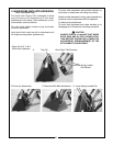
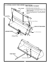
5-5 BUCKET LEVEL INDICATOR ROD
With bucket flat on level surface, fasten “L” end of
indicator rod to hole in bucket quick attach with two
flat washers and cotter pins as shown in Figure 3-3
on page 15. Install guide bracket over top end of rod
as shown. Fasten the bracket to the main frame with
5/16 x 1-1/4” bolt and locknut. Before tightening,
ensure that the “kink” in the rod is centered in the
bracket slot. This will serve as a visual indication
that the bucket is in the level position.
Figure 5-1
Mounting Bracket
27
Bracket Hole
“A”