IMPORTANT
Always keep the cylinders in a retracted position
when the loader is not in use to guard against
rust and contamination which may cause dam-
age to the cylinder rods and hydraulic system.
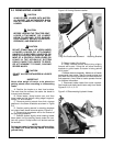
3-12 REMOVING AIR FROM HYDRAULIC
SYSTEM
Repeat raising and lowering the loader boom and
bucket operations until all the air is removed from
the system and the system responds properly.
3-13 HOSE IDENTIFICATION
Metal lines on the loader are color coded. Check
loader functions. Refer to instruction sheets for
hydraulic valve option on your loader.
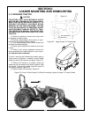
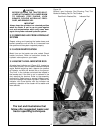
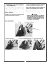
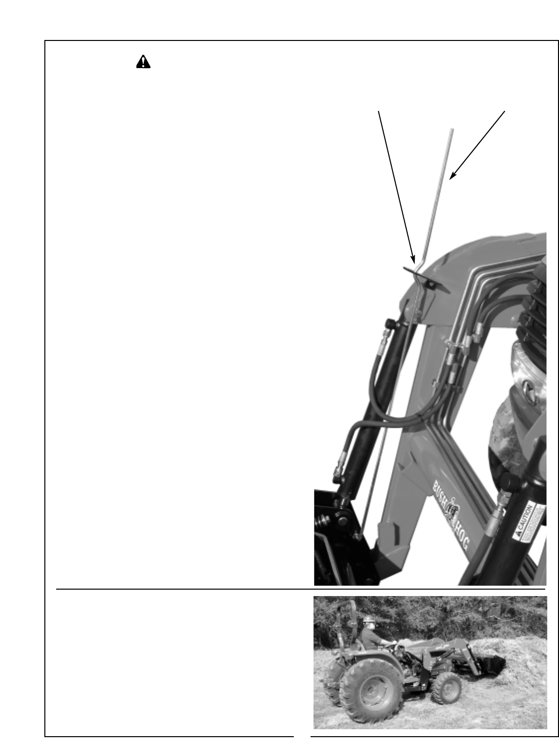
3-14 BUCKET LEVEL INDICATOR ROD
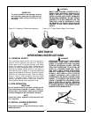
A bucket level indicator rod (Figure 3-3), located on
the bucket cylinder, can be used to determine bucket
angle. Before beginning work, observe the position
of indicator rod with the bucket flat on the ground.
The “kink” in the indicator rod should be located in
the bracket slot. If the kink is not in centered in the
slot, readjust the bracket. Refer to the assembly
instructions. Raise boom to several different posi-
tions and operate the bucket cylinders. Observe the
indicator rod. Once familiar with the indicator rod
positions, operation of the loader will be easier and
more efficient.
CAUTION
BEFORE LEAVING THE TRACTOR SEAT,
LOWER ATTACHMENT OR LOADER BOOM
TO GROUND, STOP ENGINE, LOCK
BRAKES, RELIEVE HYDRAULIC PRES-
SURE, AND REMOVE KEY.
15
Figure 3-3
Bucket Level Indicator Rod Showing That The
Bucket Is Resting Flat On The Surface
Rod Kink In Bracket Slot Indicator Rod
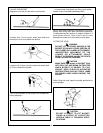
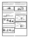
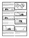
The text and illustrations that
follow offer suggested loader and
tractor operating techniques.


