


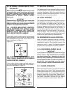
3-4 EXTERNAL LOADER AND/OR TRAC-
TOR VALVE.
NOTE
When properly installed, the tractor remote valve
or external valve control lever/levers will control
the loader hydraulic circuits as described below.
Refer to tractor Operator’s Manual for further
explanation of tractor remote control
lever/levers.
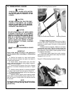
IMPORTANT
Contaminants in hydraulic fluid can cause valve
spools to stick. BE ALERT when operating
loader and follow your tractor Operator’s Manual
hydraulic fluid maintenance schedule.
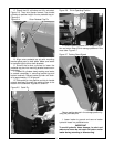
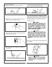
3-5 LOADER MOUNTED CONTROL
VALVE EQUIPPED WITH SINGLE LEVER
CONTROL HANDLE OR TRACTOR
REMOTE VALVE EQUIPPED WITH SIN-
GLE LEVER CONTROL HANDLE
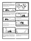
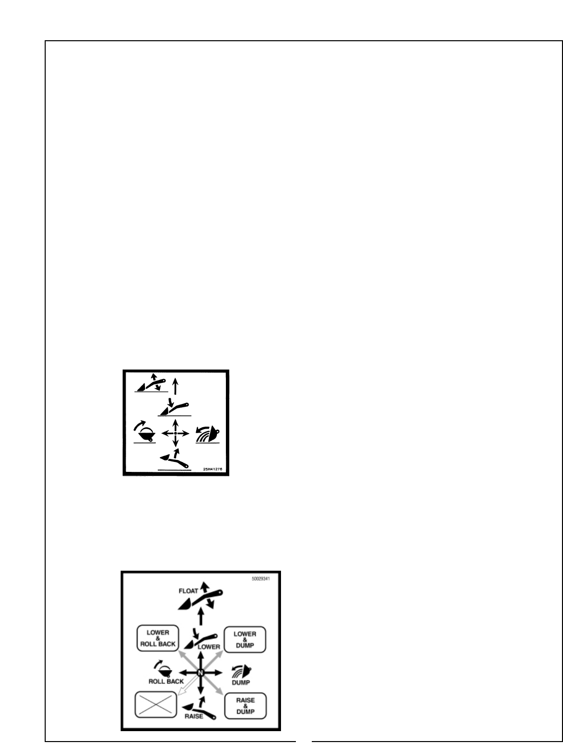
If your loader utilizes a loader control valve equipped
with single lever control handle or tractor remote
valve equipped with single lever control handle, it will
function as shown in Figure 3-1.
3-7 NEUTRAL POSITION
The loader external valve provided by Bush Hog has
a “neutral position” which prevents movement of the
loader or attachment. When the control handle is
manually released from the work position, the valve
spool will return to the neutral position.
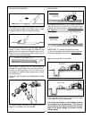
3-8 FLOAT POSITION
The loader external valve provided by Bush Hog has
a “float position” incorporated into the lift cylinder cir-
cuit which allows the loader to float. This float fea-
ture is important for satisfactory operation when
scraping, sweeping, leveling, or any job where it is
necessary to follow the contour of the surface. To
activate the float position, lower the bucket or attach-
ment and push the control handle all the way for-
ward into detent. The valve will stay in float detent
position until the operator manually pulls the control
handle out of detent position to deactivate float.
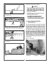
3-9 REGENERATIVE VALVE POSITION
When the handle is pushed all the way to the right,
it will go past the dump detent position into the
regenerative position. This position requires the
operator to hold it in place. This feature enhances
the performance and speed of the dump procedure.
3-10 LOAD SENSE LOADER VALVE
IMPORTANT
If your loader is equipped with a load sense type
control valve it may demonstrate the following
operation characteristic. Attempting to raise the
boom by finely feathering the control lever may
actually allow the boom to lower very slowly. To
prevent this from happening, move the control
lever far enough to ensure that the boom raises.
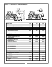
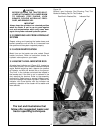
3-11 LOADER OPERATION
Before operating the loader, fully raise and lower the
boom three or four times. Then raise the loader
bucket approximately four (4) feet above the ground
and cycle the bucket two or three times. Lower the
bucket or attachment to the ground. Check the trac-
tor hydraulic fluid level and fill as required. Refer to
the tractor Operator’s Manual for the proper
hydraulic fluid and the correct hydraulic fluid level.
14
Figure 3-1
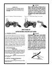
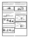
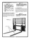
3-6 LOADER MOUNTED SERIES CON-
TROL VALVE EQUIPPED WITH SINGLE
LEVER CONTROL HANDLE
If your loader utilizes a loader mounted series con-
trol valve equipped with single lever control handle, it
will function as shown in Figure 3-2.
Figure 3-2