


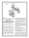

3. Remove parts bag containing bucket pins from
backhoe. Attach bucket (D) to dipperstick (B) using
one pin, 3/8” bolt, and locknut.
4. Attach bucket link (E) to bucket, using same hard-
ware as listed for step #3.
5. Reposition hoist on backhoe to prevent tipping and
raise mainframe (G) slightly. Remove all remaining
strapping and attach stabilizers (F) to mainframe (G)
using pins and hardware from parts bag.
25
6. Attach stabilizer cylinders (H) to stabilizers (F)
using pins and hardware from parts bag.
7. Using caution to prevent tipping, raise mainframe
(G) with hoist to a height of approximately 17” and
remove skid. Block mainframe (G) and swing frame (J)
securely.
8. Follow the Attaching Kit Assembly Instructions to
mount the backhoe to the tractor. Check the installa-
tion carefully and make sure that all members are cor-
rectly installed and securely fastened.
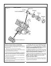
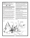
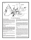
Assembly: (2165 & 2175) - Figure 12
(See “General” note, page 24)
IMPORTANT: Tighten all hardware to torque
requirements specified in torque chart on page 45.
DO NOT cut any strapping that fastens the back-
hoe mainframe and swing frame to the skid at
this time.
1. Remove the stabilizer assemblies and any miscella-
neous items which have been fastened to skid and
arrange conveniently. Be sure hoses to stabilizer cylin-
ders are routed above the cylinder-to-mainframe pivot pin
connection.
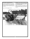
2. Support boom (A) and dipperstick (B) with hoist
attached at (C) and remove boom transport lock pin.
Lower boom and extend dipperstick until end of dip-
perstick is approximately 16” above the ground. Move
control handles to “BOOM DOWN” position and
“CROWD OUT” position as required to aid move-
ment.
Be sure hoist being used is suitable, has suffi-
cient capacity, and is in the proper position. Do
not allow anyone under a backhoe member sup-
ported by hoist.
3. Remove parts bag containing bucket pins from
backhoe. Attach bucket (D) to dipperstick (B) using
one pin, 3/8” bolt, and locknut.
4. Attach bucket link (E) to bucket, using same hard-
ware as listed for step #3.
5. Reposition hoist on backhoe to prevent tipping and
raise mainframe (G) slightly. Remove all remaining
strapping and crate base. Using caution to prevent
tipping, raise mainframe (G) to approximately 13” and
block mainframe and swing frame (J) securely.
6. Attach stabilizers (F) to mainframe (G) using pins
and hardware from parts bag.
7. Attach stabilizer cylinders (H) to stabilizers (F)
using pins and hardware from parts bag.
8. Follow the Attaching Kit Assembly Instructions to
mount the backhoe to the tractor. Check the installa-
tion carefully and make sure that all members are cor-
CAUTION
CAUTION
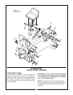
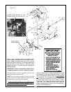
MOUNTING KITS AND OPTIONAL KITS ASSEMBLY
3- POINT HITCH LINKAGE (For 2165 & 2175)
General Description
Mounting and hydraulic kits do not include hoses to
connect the backhoe to the tractor hydraulic system.
Additional hydraulic components, hoses, and/or kits
will be required to complete the hook-up to the tractor
hydraulic system. Refer to the “Hydraulic Hook-up”
section for further information. PTO pump kits are
available as options.
Mounting Backhoe to Tractor or Skid
Steer loaders
The Bush Hog backhoe can be mounted to the power
source using three different attaching kits.
1. To an agricultural tractor’s 3-point hitch linkage
using the 3-point hitch kit. The 3-point hitch kit is the
same regardless of tractor model and the instructions
for attaching the kit to the backhoe are included
below. See Figure 13 for general appearance.
2. To an agricultural tractor using a subframe kit
specifically offered for the tractor model and backhoe
being mounted: The subframe kit instructions differ
with each tractor/backhoe combination and come
included with the individual subframe kit.
3. To a skid steer loader using a skid steer adaptor kit
offered for the skid steer model and backhoe series
being mounted. The skid steer adapter kit instructions
differ with each skid steer model/backhoe combina-
tion and come included with the individual skid steer
adapter kit.