


24
ASSEMBLY
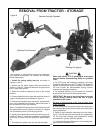
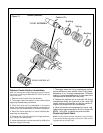
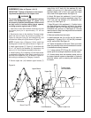
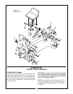
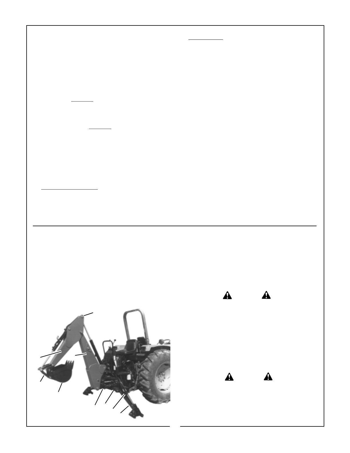
Basic components for all models can be identified in Figure 12. Refer to Page 43 for photographs of unit on shipping pallet.
General:
The backhoe has been partially disassembled and
strapped to a skid for shipping purposes. Initial installa-
tion on the tractor will require a hoist or other device
capable of safely lifting the entire backhoe from the skid.
After the initial installation is complete, the backhoe can
serve as its own erecting hoist, by lowering stabilizers
and bucket to the ground. Additional lifting devices will
not be required for normal removal and reattaching.
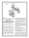
Assembly(2185 & 2195) - Figure 12
IMPORTANT: Tighten all hardware to torque
requirements specified in torque chart on page 45.
1. Remove the stabilizer assemblies and any miscellaneous
items which have been fastened to the skid and arrange
conveniently.
Be sure hoist being used is suit-
able, has sufficient capacity and
is in the proper position. Do not
allow anyone under a backhoe
member supported by hoist.
C
B
E
D
A
I
G
H
F
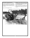
2. Support boom (A) and dipperstick (B) with hoist
attached at (C) and remove boom transport lock pin.
Lower boom and extend dipperstick until end of dip-
perstick is approximately 16” above the ground.
Move control handles to “BOOM DOWN” position and
“CROWD OUT” position as required to aid movement.
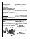
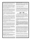
1. Remove control valve from the backhoe.
2. Thoroughly clean the exterior of the valve before
beginning disassembly procedures.
3. At the
BOTTOM of the valve remove screws, cap
and spool control kit. Keep parts in order of disas-
sembly. See figure 11 for parts involved in the make-
up of the spool control kit.
IMPORTANT: DO NOT remove the spool from the
valve. The seals can be replaced externally.
Prevent spools from rotating or moving by insert-
ing a rod through the hole in the spool and using
the rod as a handle. DO NOT
hold the spool with a
wrench. This will destroy the finish.
4. At the BOTTOM of the valve, remove the backup
ring and spool o-ring seal.
5. Thoroughly clean counterbores.
6. Install new seals:
A. Spool Control Kit Only
:
All parts inside cap are lubricated with synthetic base
grease NLGI1. Slide o-ring seal over valve spool and
insert seal in counterbore. Replace backup washer
and spool control kit.
B. Float Kit Only:
All parts inside cap are lubricated with synthetic
base grease grade NLGI2. Install new o-ring seal
over valve spool and insert seal in counterbore.
Replace backup washer, control bushing, control
spring, control bushing and positioner pin, being
careful to orient items per Figure 11.
7. At the
BOTTOM of the valve replace cap and
screws, reversing the order in which they were dis-
assembled in step 3. Torque screws to 5 ft. lbs.
8. At the top of valve remove all parts connected to
the spool (handles, linkage, etc.)
9. At the
TOP of the valve remove screws, flange,
dust cover, backup ring and spool o-ring seal.
10. Thoroughly clean counterbore.
11. Lightly oil new o-ring seal. Slide o-ring seal over
valve spool and insert seal in counterbore. Replace
backup ring, dust cover, flange and screws. Torque
screws to 5 ft. lbs.
12. Reattach all parts connected to the spool (han-
dle, linkage, etc.).
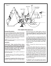
CAUTION
DO NOT cut any strapping that
fastens the backhoe mainframe
and swing frame to the skid
base at this time
CAUTION
Figure 12