


L-1914 Rev. B
15.
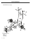
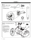
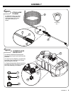
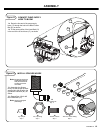
INSTALLING ELECTRICAL CONNECTIONS
(Cont’d)
4. Remove the battery leads.
5. Using the Battery Connection Wiring Harness (6) attach the
black lead and the black lead from your engine to the negative
(-) battery terminal.
6. Attach the red lead (with the fuse) of the Battery Connecting
Wiring Harness and the red lead from your engine to the posi-
tive (+) battery terminal.
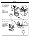
Note:The Battery Connection Wiring Harness contains a 15 amp blade type
fuse.
Note:If the battery is underneath the seat, ensure that both battery terminals
and battery leads do not make contact with seat.
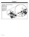
7. Attach the Wiring Harness with Switch (5) to the connector ter-
minal end of the Battery Connection Wiring Harness (6).
Note:In most instances the terminal connector with the shorter leads from the
Wiring Harness with Switch (5) are connected to the terminal connector
on the Battery Connection Wiring Harness (6). Most users like the
switch to lie in their laps or be convenient to the towing vehicle operator.
The Wiring Harness with Switch (5) terminal connectors can be
reversed to suit the need of the user.
8. Attach the other end of remaining terminal lead connector from
the Wiring Harness with Switch (5) to the terminal lead connec-
tor coming from the Pump (4). If the pump begins to run, use
the switch to turn the pump off.
Note:The Battery Connection Wiring Harness (6) can remain connected to
the battery of the towing vehicle when spraying operations are com-
plete. Simply detach the Wiring Harness with Switch (5) terminal con-
nector from the Battery Connection Wiring Harness (6) terminal
connector.
PUMP OPERATIONS
The pump motor supplied with your sprayer is a “demand flow”
type pump. An internal pressure switch in the pump turns the pump
off when the pressure reaches approximately 60psi. When the
pump senses that pressure has dropped (by triggering the wand)
the pump will again start and continue to run until 60psi is reached.
Note:Pump surge should be avoided. It can cause the pump motor to over-
heat resulting in damage to the pump. Refer to the Wand Operations
Section for tips on how to avoid pump surge.
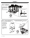
WAND OPERATIONS
The wand can be used for spraying in various applications from a
steady stream to a fine mist. Adjust the spray pattern by turning the
Wand Tip (31) clockwise for a fine mist or counterclockwise for a
course spray.
Pump Surge
Pump surge may occur when using the wand for fine mist applica-
tions. Do not allow this to occur. The pump is designed for continu-
ous duty. Intermittent starting and stopping will cause the pump
motor to overheat. To eliminate pump surge:
a) Open the wand tip to a higher flow rate
b) Create a by-pass that allows the pump to run continuous by
removing one of the boom hoses near the tip (See Step 11).
Remove the tank fill cap and place the hose in the tank. Open
the valve for the boom slowly until the pump runs continu-
ously. Adjust the wand tip to the desired mist.
BOOM OPERATIONS
Boom spraying is the normal spraying configuration and is con-
trolled by the operator in the seated position.
For spraying in a vertical orientation such as along fences or
hedges, use the wand operation.
APPLICATION RATE
Wand
Understanding the following information about your sprayer will
help to calibrate the application rate. The sprayer operates at a
fixed pressure of 60 psi. This results in actual spraying time of 30
minutes using the handgun.
Boom
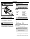
CAUTION:
Avoid Injury! Avoid injury! Care
should be when routing the wiring harness to the
sprayer.
Do not place the wiring harness in areas that the
wires can be pinched or damaged.
Place the wires to minimize a tripping hazard when
getting on or off the towing vehicle.
CAUTION:
Avoid Injury! Always turn pump off
when making adjustments to the Wand Tip. Wear
eye protection.
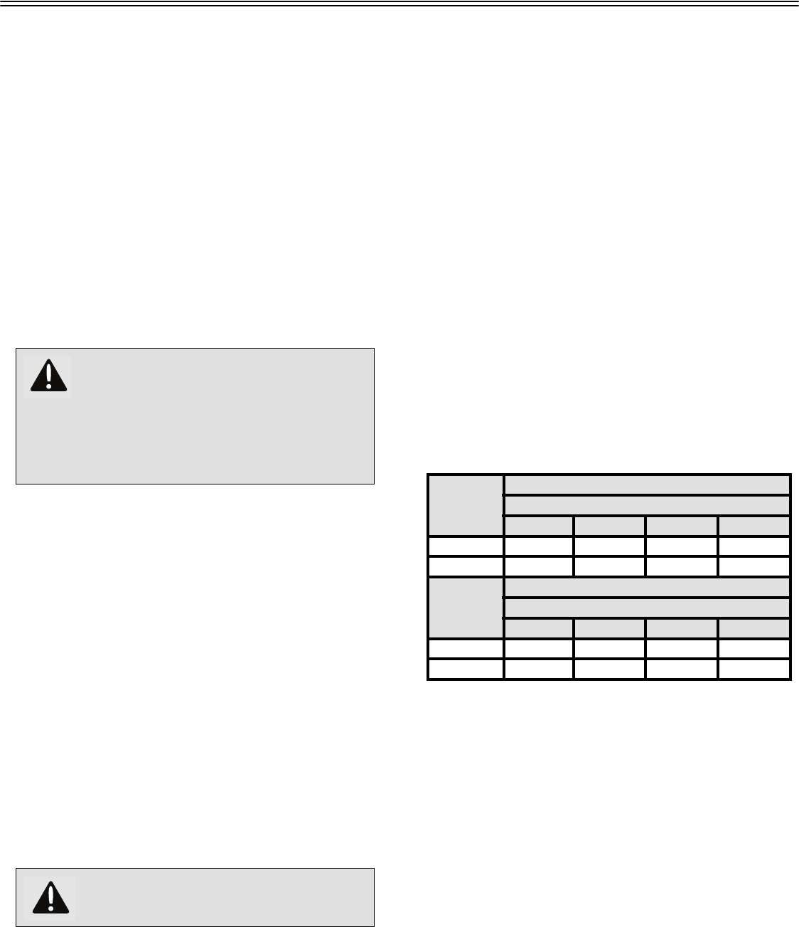
Table 1:
Product
Gallons Per Acre
MPH
2 3 4 5
ST-151BH 56.5 37.5 28.0 22.5
ST-251BH 56.5 37.5 28.0 22.5
Product
Gallons Per 1000 Square Feet
MPH
2 3 4 5
ST-151BH 1.3 0.9 0.6 0.5
ST-251BH 1.3 0.9 0.6 0.5
OPERATION