


Assembly Instructions
18
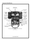
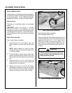
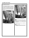
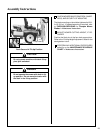
PTO Shaft Guard Installation
Position the shaft guard as shown and mount with
two 1/4-20 x 1/2 in. bolts.
PTO Shaft Guard Installation
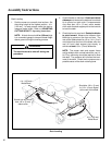
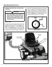
Tilt-Up Roller Wheel Installation
NOTE: A 2-1/2" diameter tilt-up roller wheel
(P/N 9772) is required for decks installed on the
Model MB tractor.
Mount the two (2) tilt-up roller wheels on the brack-
ets on the rear skirt of the deck housing using the
P/N 8490 axle bolt, 3/8 in. wave spring washer and
3/8-16 in. Whiz locknut. Tighten the axle bolt until
the wheel rolls freely, but is not loose.
Roller Wheel Installation
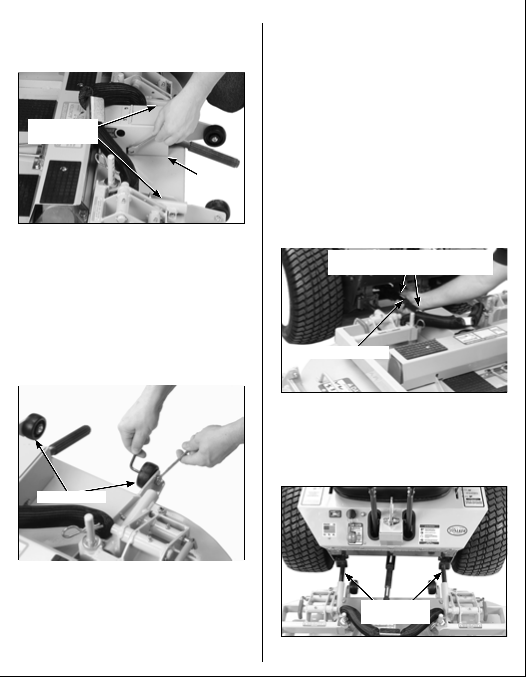
Mower Deck Installation on Tractor
Deck Installation
1. Lightly grease each deck support arm (2) on the
tractor. Refer to Mower Deck Installation photo
for location of deck support arm.
2. Engage the deck carrier frame tube sockets on
the tractor support arms (refer to PTO Shaft
Guard Installation photo for socket location).
Slide the deck onto the support arms approxi-
mately 3 in. (76 mm).
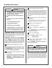
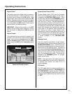
3. Align and connect the splined PTO shaft and
socket halves, as shown in PTO Shaft Connec-
tion photo. The PTO shaft has a pilot end to ease
alignment of shaft; fit shaft end into socket and
rotate shaft until the splines line up as indicated
by arrows, then slide together.
PTO Shaft Connection
4. Install the hitch pin through the hole on the end
of each support arm to lock the deck in place (re-
fer to Deck Counterweight Spring Installation
photo). Two (2) hitch pins are included in the
owner’s packet of materials.
Mower Deck Installation
Carrier Frame
Tube Sockets
Attach
Guard
Roller Wheels
PTO Connection
Arrows on Shaft and Tube
(used to align when sliding together)
Deck Support
Arms