


12
Briggs & Stratton Power Products Home Generator System
Owners Manual
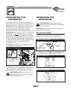
4A. For electric starting, press start switch on generator
cradle.To prolong the life of the starter components,
press the starter button for no more than 15 seconds,
and pause for 30 seconds.
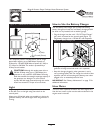
4B. For manual starting, grasp starter grip and pull slowly
until you feel some resistance.Then pull cord out with
rapid full arm stroke. Let rope return slowly. Do Not
let rope “snap back” against starter.
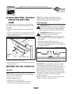
5. If the choke lever has been moved to the “Choke”
position to start the engine, gradually move it to the
“Run” position as the engine warms up.
NOTE: If engine still fails to start after 3 pulls, check for
proper oil level in crankcase.This unit is equipped with a
Low Oil Shutdown System. See engine manual.
Refer to the engine owner’s manual for complete
starting instructions.
Connecting Electrical Loads
• Let engine stabilize and warm up for a few minutes after
starting.
• Turn ON the generator main breaker to energize the
30 Amp connector.
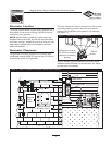
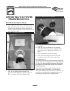
• Connect the unit to the power inlet box, following the
connection instructions given in the section “Switch to
Generator Power” on page 15. Or plug in and turn on
the desired 120 and/or 240 Volt AC, single phase,
60 Hertz electrical loads.
• Do Not connect 240 Volt loads to the 120 Volt
receptacles.
• Do Not connect 3–phase loads to the generator.
• Do Not connect 50 Hz loads to the generator.
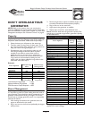
• DO NOT OVERLOAD THE GENERATOR. When
not used with the semi-automatic transfer switch, add up
the rated watts (or amps) of all loads to be connected at
one time.This total should not be greater than the rated
wattage/amperage capacity of the generator. See “Don’t
Overload the Generator” on page 14.
Stopping the Engine
• Unplug all electrical loads from generator panel
receptacles. Never start or stop engine with electrical
devices plugged in and turned on.
• Let engine run at no–load for 30 seconds to stabilize the
internal temperatures of engine and generator.
• Move the fuel valve to the “Off” position.
• Wait for the engine to idle down.
• Move the rocker switch to the “Stop” position.
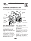
RECEPTACLES
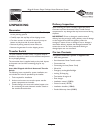
120 Volt AC, 20 Amp, Duplex
Receptacle
Each receptacle (Figure 11) is protected against overload by
a 20 Amp push–to–reset circuit breaker.
Use each receptacle to operate 120 Volt AC, single–phase,
60 Hz electrical loads requiring up to 2400 Watts (2.4 kW)
at 20 Amps of current. Use cord sets that are rated for
125Volt AC loads at 20 Amps (or greater).
120/240 Volt AC, 30 Amp, Locking
Receptacle
Use this plug to connect the unit to the connection box
with the supplied cord.
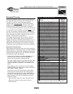
A NEMA L14–30 plug is used with this receptacle. Connect
a 4–wire cord set rated for 250 Volt AC loads at 30 Amps
(or greater) (Figure 12).You can use the same 4–wire cord
if you plan to run a 120 Volt load.
Figure 11 — 120 Volt AC, 20 Amp, Duplex Receptacle