


37
Troubleshooting, Adjustment & Service
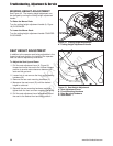
REAR SUSPENSION ADJUSTMENT
The shock assembly can be adjusted in two ways to
allow the operator to customize the ride according to
operator’s weight and/or operating conditions. You
have the option of adjusting the spring pre-load and/
or the upper mounting position.
Items to consider before adjusting the suspension.
• Less spring pre-load should be used with light
weight operators, which will provide a softer, more
cushioned ride.
• More spring pre-load or upper mounting position
#2 should be used with heavy weight operators.
To adjust the spring pre-load:
1. Park machine on a flat, level surface. Disengage
the PTO, stop the engine and engage the parking
brake.
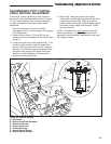
2. See Figure 32. Using the supplied spanner
wrench (p/n 5022853), insert the tip of the wrench
into the notch in the pre-load adjuster. While
holding the wrench in place with one hand, turn
COUNTER-CLOCKWISE to increase the pre-load,
turn CLOCKWISE to decrease the pre-load.
NOTE: Spanner wrench is located in the publication
packet with this manual.
To adjust the upper mounting position:
1. Park machine on a flat, level surface. Disengage
the PTO, stop the engine and engage the parking
brake.
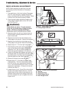
2. Place a 50 lbs (22.7 kg) weight on the front of the
deck.
3. While standing to the side of the machine use
the mower deck lift actuator switch located on the
control panel to raise the deck. With no operator
present in the seat and the additional weight on
the front of the deck, raising the deck with the
mower deck lift actuator switch will cause the rear
of the machine to raise off of the floor.
4. Place wooden blocks underneath the rear tire.
5. Use the mower deck lift actuator switch to lower
the deck. With no operator present in the seat
and the additional weight on the front of the
deck, lowering the deck with the mower deck lift
actuator switch will cause the rear of the machine
to be lowered towards the ground. Slowly lower
the deck until the rear steering wheel rests on
the blocks and the pressure on the upper shock
mounting bolt is relieved.
NOTE: The shock should move freely on the
mounting bolt when the pressure is relieved.
6. Remove the upper shock mounting hardware and
pivot the shock to the position #2 (see Figure 28).
7. Reinstall the upper shock mounting hardware and
tighten securely.
8. Remove the wooden blocks from under the rear
steering tire.
9. Remove the 50 lbs (22.7 kg) weight from the front
of the deck.
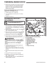
WARNING
Use two hands when adjusting the shock
springs. This will prevent the wrench from
slipping while pressure is being applied.
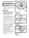
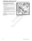
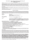
Figure 32. Rear Suspension Adjustments
POSITION #1
(FACTORY SET)
POSITION #2
Not for
Reproduction