


31
Troubleshooting, Adjustment & Service
B
C
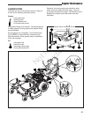
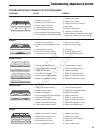
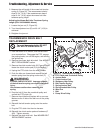
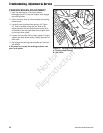
Figure 21. Mower PTO Belt Routing
A. Spindle Pulley
B. PTO Drive Belt
C. Stationary Idler Pulley
D. Spring-loaded Idler Pulley
A
D
A
A
C
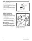
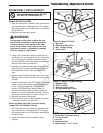
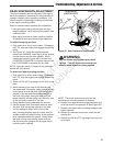
Figure 20. Mower PTO Belt
A. Idler Arm
B. Stationary Idler Pulley
C. Idler Tension Spring
D. Anchor Bolt
B
A
D
C
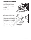
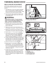
MOWER BELT REPLACEMENT
Mower Deck Drive Belt
1. Park the machine on a smooth, level surface such
as a concrete floor. Disengage the PTO, engage
the parking brake, turn off the engine, and remove
the ignition key.
2. Remove the mower deck guard.
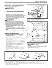
3. Using a 3/4” combination wrench, place the box
end on the 1/2” nut located on the end of the idler
arm (A, Figure 20). Carefully rotate the breaker
bar CLOCKWISE, which will relieve the tension on
the belt exerted from the idler arm.
4. Slide the drive belt over the edge of the stationary
idler pulley (B). Carefully release the tension on
the breaker bar until the idler arm comes to a
stop.
6. Remove the old belt and replace with a new one.
Make sure the V-side of the belt runs in the pulley
grooves.
7. Install the drive belt on the PTO pulley, the spindle
pulleys, and all idler pulleys except the stationary
pulley. Carefully rotate the 3/4” combination
wrench CLOCKWISE and install the belt on
the stationary idler pulley. Carefully release the
tension on the 3/4” combination wrench. The belt
should be routed exactly as shown in Figure 21.
8. Reinstall the mower deck guard.
9. Run the mower under no-load condition for about
5 minutes to break-in the new belt.
Check the Mower Belt Idler Tensioner Spring
Length (S/N: 2015249869 & Above)
1. Park the machine on a smooth level surface such
as a concrete floor. Disengage the PTO, engage
the parking brake, turn off the engine and remove
the ignition key.
2. Lower the mower deck to its lowest cutting
position.
To avoid damaging belts, DO NOT
PRY BELTS OVER PULLEYS.
WARNING
Use extreme caution when rotating the idler
arm with the combination wrench, due to the
increased tension in the spring as the idler
arm is being rotated. Injury may result if the
combination wrench is prematurely released
while the spring is under tension.
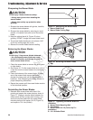
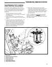
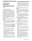
Figure 22. Mower Belt Idler Spring Length
A. Mower Belt Tensioner Spring
B. Anchor Eyebolt
C. Jam Nut
D. Adjustment Nut
E. Measurement - 6-1/4” (15,9)
E
C
D
B
A
Not for
Reproduction