


14
Normal Removal
& Installation
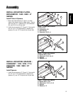
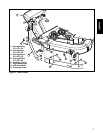
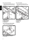
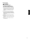
A. Hitch Support Assembly
B. Cover K. Nut & Capscrew
C. Pin L. Mounting plate
D. Hair Pins M. Lower Chute Rod
E. Bag N. Lower Chute
F. Grass Bag Hanger O. Pin
G. Upper Tube P. Strap, Middle
H. Middle Tube Q. Ridge
I. Strap, Boot R. Ridge Cutout
J. Deflector S. Rear Spacers
E
Q
D
B
Normal Removal & Installation
Collector Installation
Note: See previous pages for more detailed
installation and operation instructions if necessary.
1. Mount the hitch support assembly (A, Figure 17)
onto rear tractor frame spacers (S).
2. Attach cover (B) to support assembly using pins
(C) and hair pins(D).
3. Pivot cover (B) up. Install bags (E) by attaching
grass bag hanger (F) to support assembly (A).
Figure 17. Normal Installation & Removal
C
P
I
N
O
M
L
J
R
A
K
4. Lift discharge deflector (J) up. Insert lower chute
rod (M) into mounting plate (L). Pull strap (I) and
secure by placing hole closest to knob in strap
completely over locknut and capscrew (K).
5. Slide the upper tube (G) into cover (B) aligning
ridge (Q) with cutout (R) as shown.
6. Slide middle tube (H) into upper tube (G). Slide
middle tube (H) over lower chute (N). Pull strap
(P) and place hole completely over pin (O).
F
G
H
D
C
Normal Removal & Installation
S
S