


8
Assembly
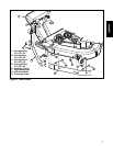
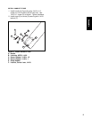
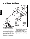
Figure 8. Install Lower Chute and Pin to Boot
A. Pin, Latch
B. Carriage Bolt, 1/4-20 x 5/8
C. Locknut, 1/4-20
D. Lower Chute
E. Locknut, Center Lock, 5/16-18
F. Strap, Rubber
G. Locknuts, Whiz Lock, 5/16-18
H. Rod, Boot Mount
I. Capscrew, Hex Head, 5/16-18 x 1-1/4
J. Capscrew, Hex Head, Thin, 5/16-18 x 1
D
B
C
F
A
G
G
H
I
J
E
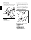
INSTALL LOWER CHUTE ROD AND PIN TO BOOT
1. Insert the head of pin (A, Figure 8) through front
hole of lower chute (D). Secure with 1/4-20 x 5/8
carriage bolt (B) and 1/4-20 lock nut (C) as
shown.
2. Install the rod (H) to lower chute (D) using 5/16-18
x 1 capscrew (J) and 5/16-18 locknut (G) for front
holes. Use 5/16-18 x 1-1/4 capscrew (I) and 5/16-
18 locknut (G) as shown. Tighten hardware.
3. Install the rubber strap (F) onto capscrew (I)
securing with 5/16-18 locknut as shown.
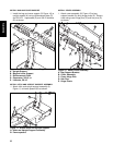
Install Components
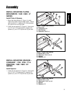
INSTALL MOUNTING PLATE
1. Install mounting plate (A, Figure 7) to mower deck
as shown. Secure with 5/16-18 x 5/8 carriage
bolts (C) and 5/16-18 locknuts (A).
Figure 7. Install Mounting Plate
A. Mounting Plate
B. Locknuts, 5/16-18
C. Carriage Bolts, 5/16-18 x 5/8
C
B
A