4
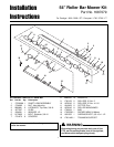
Installation Instructions Roller Bar Mower Kit
Removing the Mower Deck
1. Park the tractor, fully lower the attachment lift, turn off
the PTO, turn off the engine, remove the key, and
engage the parking brake. If equipped, pivot the
gauge wheels into sliding position (see Figure 4).
2. Place mower in the lowest cutting position using the
mower height control.
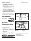
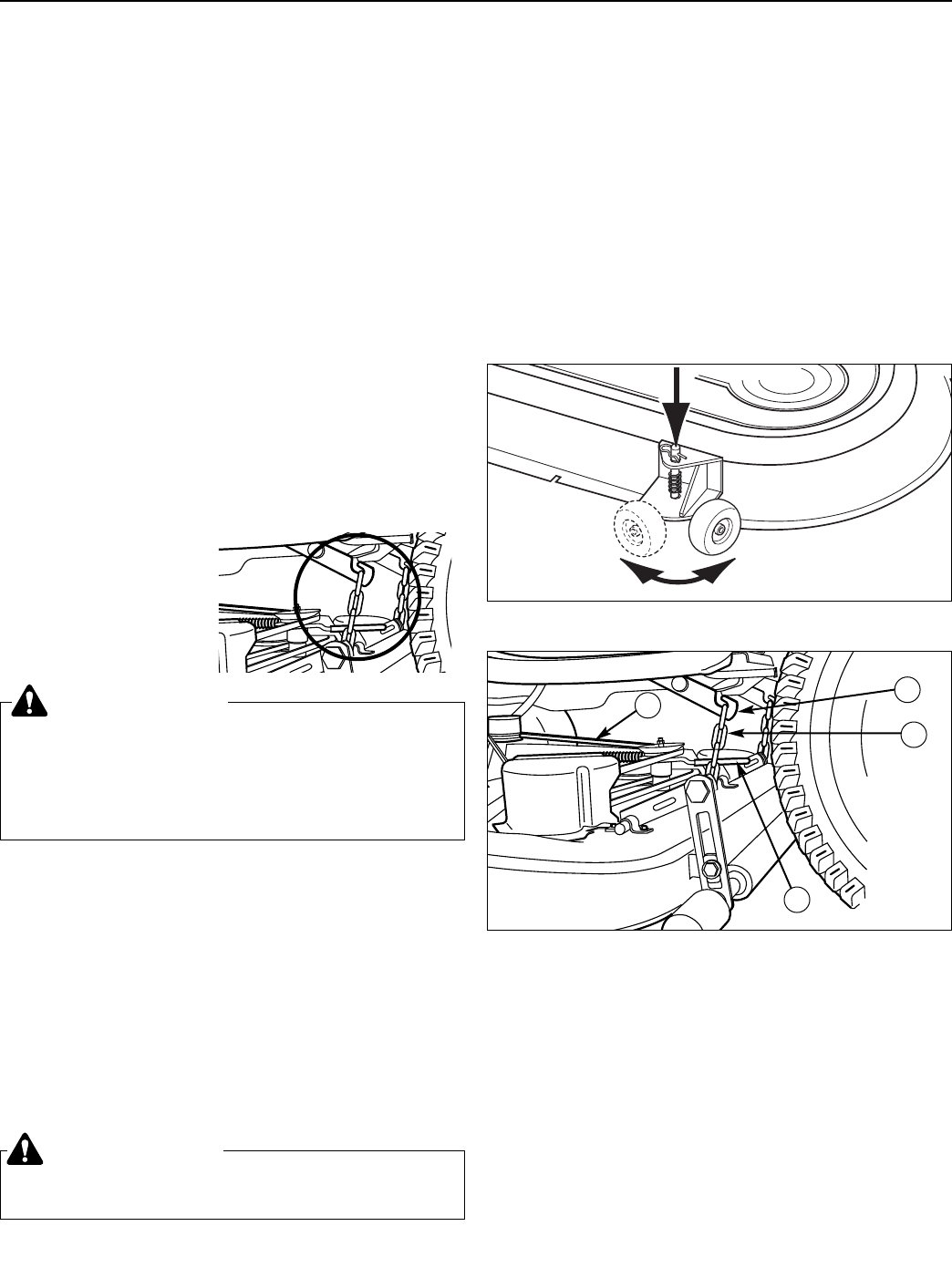
3. Use the idler arm (D, Figure 5) to release tension on
the PTO belt, and remove belt from the PTO pulley.
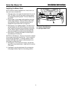
4. Pull down on the lift hooks (A, Figure 5) and unhook
the lift chains (B).
WARNING
Engage parking brake, disengage PTO, stop
engine and remove key before attempting to
install or remove the mower.
Muffler and surrounding areas may be hot.
A
B
C
D
Figure 4. Pivoting Gauge Wheels - Select Models
Figure 5. Mower Lift
A. Lift Hook C. PTO Belt
B. Lift Chain D. Idler Arm
MOWER DECK REMOVAL &
INSTALLATION
Chain Lift Models
CAUTION
The muffler and surrounding areas may be hot.
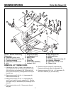
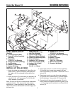
6. Connect the LH side roller bar assembly (P) to LH
side of mower deck (Y) securing with 3/8-16 x 1-
11/32 shoulder bolt (X), 1/2 washer (W), slide (V),
and 3/8-16 locknut (Q).
7. Attach height of cut plate (E) and arm (F) to rocker
arm assembly (M). Secure with 5/16-18 x 1-1/4 cap-
screws (D) and 5/16-18 nuts & washers (I).
8. Attach the trunnion support (B) to mower deck (Z).
Secure with 5/16-18 x 3/4 capscrews (A).
9. Attach the upstops (H) to mower deck (Z). Secure
with 5/16-18 x 3/4 capscrews (A) and washers (G).
10. Attach adjustment rod (L) to rocker arm assembly (M)
using clevis pin (K) and hair pin (J).
Refer to the Mower Deck Removal & Installation section
in these instructions to install and level mower deck.
Retain these instructions as a supplement to the original
Operator’s Manual.
5. Turn the wheels straight ahead. Pull back on spring-
loaded lever (B, Figure 6) and lift mower hitch off of
the tractor brackets (A).
6. Turn wheels fully left, and slide mower deck out from
under the right side of the tractor.


