


3
Roller Bar Mower Kit Installation Instructions
C
B
A
F
E
G
H
M
J
K
L
P
O
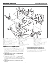
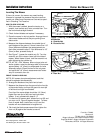
Figure 3. Install 54” Roller Bar
A. Capscrews, 5/16-18 x 3/4
(Existing)
B. Trunnion Support (New)
C. Crank & Trunnion Assembly
(Existing)
D. Capscrews,
5/16-18 x 1-1/4 (Existing)
E. Height of Cut Plate (Existing)
F. Arm (Existing)
G. Washer, 5/16 (Existing)
H. Upstop (Existing)
I. Nuts, 5/16-18 &
Lockwashers (Existing)
J. Hair Pins (Existing)
K. Clevis Pins (Existing)
L. Adjustment Rods (Existing)
M. Rocker Arm Assembly (New)
N. Straps (Existing)
O. Locknuts, 1/2-13 (Existing)
P. Roller Bar Assembly (New)
Q. Locknut, 3/8-16 (New)
R. Carriage Bolt,
3/8-16 x 1-1/2 (New)
S. Chains, 4 Link (Existing)
T. Capscrews,
5/16-18 x 1-1/2 (Existing)
U. Locknuts, & Washers (Existing)
V. Slide (New)
W. Washer, 1/2 (New)
X. Shoulder Bolt,
3/8-16 x 1-11/32 (New)
Y. Mower Deck (Existing)
Z. Eccentric Nut (New)
I
Q
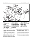
INSTALL 54” ROLLER BAR
1. Attach the rocker arm assembly (M, Figure 3) to the
mower deck (Y) with the straps (N) and capscrews
(A). Apply a thin film of grease to the inside of the
straps.
2. Attach the chains (S) to the rocker arm assembly (M)
using 5/16-18 x 1-1/2 capscrews (T), 5/16-18 lock-
nuts & washers O) as shown.
Note: The four-link lift chain is bolted to the mower deck
using the third link. This is correct for most mowing
applications. If mowing ditches or other surfaces that
require the mower to travel below its normal range, use
the fourth link.
R
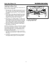
3. Place upper trunnion on crank & trunnion assembly
(C) through hole in rocker arm assembly (M) and
roller bar assembly (P) as shown. Secure with 1/2-13
locknut (O).
4. Place lower trunnion on crank & trunnion assembly
(C) through hole in mower deck (Y) roller bar assem-
bly (P) as shown. Secure with 1/2-13 locknut (O).
5. Connect the LH side roller bar assembly (P) to LH
side of rocker arm assembly (M) securing with 3/8-16
x 1-1/2 carriage bolt (R), eccentric nut (Z) and 3/8-16
locknut (Q).
A
A
N
S
T
U
U
X
W
Q
V
Y
Z
D
I