


6
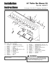
Installation Instructions Roller Bar Mower Kit
Leveling The Mower
If the cut is uneven, the mower may need leveling.
Unequal or improper tire pressure may also cause an
uneven cut. Make sure tire pressure is correct as speci-
fied in Checking Tire Pressure.
SIDE-TO-SIDE LEVELING
1. With the mower installed, place the tractor on a
smooth, level surface such as a concrete floor. Turn
the front wheels straight forward.
2. Check for bent blades and replace if necessary.
3. Place the mower in mid-cut position. Arrange the out-
side mower blades so that they are pointing from
side-to-side.
4. Measure the distance between the outside tips of
each blade and the ground. If there is more than 1/8”
(3mm) difference between the measurements on
each side, proceed to step 5. If the difference is 1/8”
(3mm) or less, proceed to step 6.
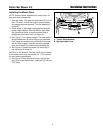
ECCENTRIC NUT MODELS
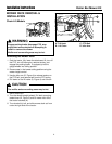
5. See Figure 8. Loosen the outside nut (A). Turn the
eccentric nut (B) to raise or lower left-hand side of
mower. When mower is level, hold the eccentric nut
while tightening the outside nut.
NOTE: 44”, 50”, & 54” Mowers. When using a turbo col-
lection system, raise the discharge side of the mower
approximately 1/4” (6mm) to compensate for turbo
assembly weight. Check the level of the cut grass and
adjust the 1/4” (6mm) measurement as necessary for a
smooth, even cut.
FRONT-TO-BACK LEVELING
NOTE: 54” mowers have two adjustment rods that
should be adjusted simultaneously.
6. Arrange the blades so they face front-to-back.
7. Measure the distance from the ground to the front tip
of the center blade, and from the ground to rear tips
of left-hand and right-hand blades.
Front tip of the center blade should be 1/4" (6mm)
higher than rear tips of left-hand and right-hand
blades. If not, proceed with steps 8 - 9.
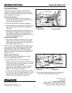
8. To raise front of mower deck, loosen front nut (B) and
turn rear nut (A, Figure 10) against bracket. To lower
front of mower deck, loosen rear nut (A) and the
bracket will move backwards to lengthen rod.
Figure 8. Leveling The Mower Side-to-Side Eccentric
Nut Models
A. Outside Nut B. Eccentric Nut
Figure 10. Front to Back Leveling
A. Rear Nut B. Front Nut
A B
9. Re-check the blade measurement then tighten the
front nut (B) against the bracket to secure.
MANUFACTURING, INC.
500 N Spring Street / PO Box 997
Port Washington, WI 53074-0997 USA
Form No. 1727716
Revision:02
TP 200-4144-02-SK-SMAN
Briggs & Stratton Yard Power Products Group
Copyright © 2007 Briggs & Stratton Corporation
Milwaukee, WI USA. All Rights Reserved
B
A