


3
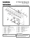
Roller Bar Mower Kit Installation Instructions
C
B
A
D
F
E
G
H
M
J
K
L
P
O
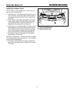
Figure 3. Installation 44” Rollers
A. Capscrews, 5/16-18 x 1-1/4
B. Washer, Large, 5/16
C. Indicator
D. Mower Support Plate
E. Crank & Trunnion Assembly
F. Capscrew, 5/16-18 x 1-1/4
G. Arm
H. Height of Cut Plate
I. Nut & Lockwasher
J. Hair Pin
K. Clevis Pin
L. Adjustment Rod
M. Rocker Arm Assembly
N. Straps
O. Locknuts, 1/2-13
P. Roller Bar Assembly
Q. Eccentric & Locknut, 3/8-16
R. Carriage Bolt, 3/8-16 x 1-1/2
S. Washer, Small, 5/16
T. Upstop
U. Capscrew, 5/16-18 x 1-1/2
V. Chain, 2 Link
W. Locknut, 5/16-18
X. Slide
Y. Washer, 1/2
Z. Shoulder Bolt, 3/8-16 x 1-11/32
I
Q
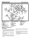
INSTALLATION 44” ROLLERS
1. Attach the rocker arm assembly (M, Figure 3) to the
mower deck with the straps (N), washers (S), upstop
(T), and capscrews (A). Apply a thin film of grease to
the inside of the straps.
2. Attach the chains (V) to the rocker arm assembly (M)
using 5/16-18 x 1-1/2 capscrews (U), washers (Y),
and 5/16-18 locknuts (W) as shown.
3. Place upper trunnion on crank & trunnion assembly
(E) through hole in rocker arm assembly (M) and
roller bar assembly (P) as shown. Secure with 1/2-13
locknut (O).
4. Place lower trunnion on crank & trunnion assembly
(C) through hole in mower deck and roller bar assem-
bly (P) as shown. Secure with 1/2-13 locknut (O).
R
A
N
T
S
U
B
V
B
W
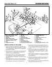
5. Connect the LH side roller bar assembly (P) to LH
side of rocker arm assembly (M) securing with 3/8-16
x 1-1/2 carriage bolt (R) and eccentric & 3/8-16 lock-
nut (Q).
6. Connect the LH side roller bar assembly (P) to LH
side of mower deck securing with 3/8-16 x 1-11/32
shoulder bolt (Z), 1/2 washer (Y), slide (X), and 3/8-
16 locknut (Q).
7. Attach height of cut plate (H) to rocker arm assembly
(M). Secure with 5/16-18 x 1-1/4 capscrews (F) and
nuts & washers (I).
8. Attach the mower support plate (D) and indicator (C)
to mower deck. Secure with 5/16 washer (B) and
5/16-18 x 1-1/4 capscrews (A).
9. Attach adjustment rod (L) to rocker arm assembly (M)
using clevis pin (K) and hair pin (J).
Z
Y
X
Q
U
B
V
B
W