


2
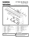
Installation Instructions Roller Bar Mower Kit
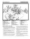
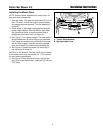
REMOVAL 44” FRAME HUNG
COMPONENTS
1. Disconnect hair pin (O, Figure 2) and clevis pin (R)
from adjustment rod (S). Remove adjustment rod (S)
from rocker arm assembly (T). Reconnect hair pin
(O) and clevis pin (R) into adjustment rod (S) to pre-
vent loss.
2. Remove and retain 5/16-18 x 1-1/4 capscrews (A),
washer (B) and indicator (C). Remove and discard
wheel bracket (G).
3. Remove and retain 5/16-18 x 1-1/4 capscrews (J),
arm (K) and crank & trunnion assembly (I). Remove
and retain nut (N), lockwasher (M) and height of cut
plate (L).
C
B
A
G
I
J
K
L
Y
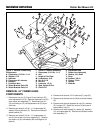
Figure 2. Remove Frame Hung
Components
A. Capscrews, 5/16-18 x 1-1/4
B. Washer, 5/16
C. Indicator
D. Capscrews & Locknuts
E. Hangers
F. Eccentric Nuts
G. Wheel Bracket Plate, RH
H. Wheel Bracket Plate, LH
I. Crank & Trunnion Assembly
J. Capscrews, 5/16-18 x 1-1/4
K. Arm
L. Height of Cut Plate
M. Lockwasher, 5/16
N. Nut, 5/16-18
O. Hair Pin
P. Locknuts, 1/2-13
Q. Stop, Height Of Cut
R. Clevis Pin
S. Adjustment Rod
T. Rocker Arm Assembly
U. Washer, 3/8, Small
V. Strap
W. Locknut, 3/8-16
X. Chains, 3 Link
Y. Upstop
Z. Washers
W
R
S
A
Q
O
D
M
P
N
4. Remove and discard 1/2-13 locknuts (P), stop (Q).
5. Remove and discard locknut (W) and wheel bracket
(H).
6. Remove and discard capscrew & nuts (D), washers
(Z), hangers (E). Retain the chains (X) and one of
the eccentric nuts (F).
6. Remove and retain straps (V), upstop (Z), washers
(U), and capscrews (A). Remove and discard rocker
arm assembly (T).
T
U
V
H
X
E
Z
F
D
D
X
E
F
D