


12
www.briggsandstratton.com
GFCI
MAIN BREAKER
PUSH
TO
RESET
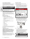
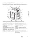
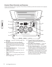
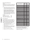
Control Panel Controls and Features
Compare this illustration with your generator’s Control Panel, to familiarize yourself with the locations of the receptacles,
controls and circuit breakers:
A - LED Light — Generator is producing voltage when
illuminated.
B - Ground Fault Circuit Interrupter/Breaker —
Protects the generator from over-current conditions
electrical faults to ground and must be in the “ON”
position to supply power to all of the control panel
receptacles.
C - START/RUN/STOP Switch — This three-position
switch is used as follows:
•“START” position starts the generator. Press and
hold to start generator.
•“RUN” position is switch position while generator is
running.
•“STOP” position turns off the generator. Press and
hold until engine stops.
D - 120/240V 30 Amp Locking Receptacle —
Supplies the total generator output power and is
GFCI protected.
E - Push-to-Reset Circuit Breakers — Protects the
generator from current overload at receptacle.
F - 120 Volt 20 Amp Receptacles — Each receptacle
can supply a maximum of 20 amperes of power. The
120 Volt receptacles are GFCI protected. Total load
on all four receptacles cannot exceed 7000 watts.
G - 15 Amp Fuse — Protects the generator DC control
circuits. If the fuse has melted open or was removed,
the engine cannot crank or start. Replace the fuse
using only an identical ATO-type 15A fuse, available
from most automotive parts stores.
120/240V 30A
G
C
A
E
E
E
F
D
B
PUSH
TO
RESET
120V 20A
ALL RECEPTACLES GFCI-PROTECTED
120V 20A
15A FUSE
START/RUN/STOP