


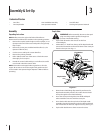
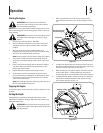
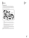
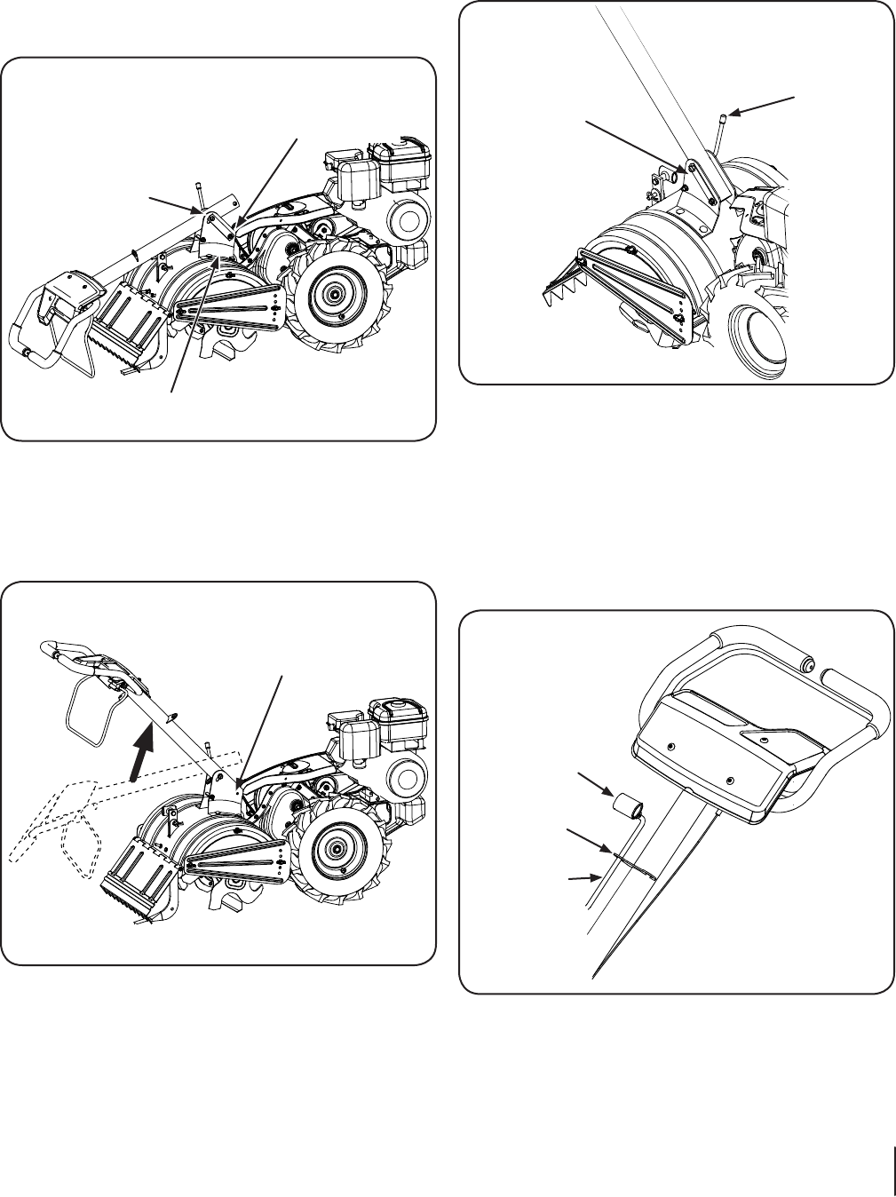
Handlebar Assembly
Remove the handle adjustment crank, flange nut, retainer
bracket, shoulder bolt, and lock nut from the pivot bracket.
Place the handle assembly into position in the handle pivot
bracket by lining up the upper holes in the handle with the
slots in the pivot bracket. See Fig. 3-2.
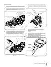
Lift up the handle assembly and align the bottom holes in
the handle assembly with the holes in the pivot bracket.
Insert the shoulder bolt from the left side of the tiller
through the pivot bracket and the retainer bracket on the
right hand side of the tiller. See Fig. 3-3.
1.
2.
3.
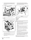
Place the hex opening of the flange nut retainer bracket
over the flange nut securing the handle adjustment crank
and install the lock nut on the lower shoulder bolt. See Fig.
3-4.
Pivot the handle assembly into the desired position.
Tighten the bottom bolt, lock nut, and the handle
adjustment lock securely.
Gear Shift Rod
Remove the T-handle, cotter pin, flat washer and rubber
washer from the end of the gear shift rod.
Slide the rod up through the right side of bracket on the
front of the handle assembly. See Fig. 3-5.
4.
5.
1.
2.
Retainer Bracket,
Shoulder Bolt
& Lock Nut
Handle Adjustment Crank
& Flange Nut
Pivot Bracket
Figure 3-2
Retainer Bracket,
Shoulder Bolts
& Lock Nut
Figure 3-3
Handle Adjustment
Crank
Flange Nut
Retainer Bracket
Figure 3-4
T-Handle
Bracket
Gear Shift Rod
Figure 3-5
7sectiOn 2 — asseMbly & set-up